- Catalogs
- Angst+Pfister Sensors and Power AG
- PBM210-A20K Series
- Company
- Products
- Catalogs
- News & Trends
- Exhibitions
PBM210-A20K Series
1 /14Pages

PBM210-A20K Series
1 /14Pages
Catalog excerpts

Features □ Supply voltage: 1.7 to 5.5V(Vdd) 1.2 to 5.5V(Vddio) □ Absolute pressure range 30 to 200 kPa □ 2.2ms fastest conversion time □ Calibrated and temperature compensated Application Examples □ Indoor and outdoor navigation □ Weather forecast device □ Altimeter and barometer for portable device □ Bike computer Descriptions The PBM210 is a new generation of high resolution digital barometer. The PBM210 is a digital pressure sensor which consists of a MEMS piezoresistive pressure sensor and a signal conditioning ASIC. The ASIC include a 24bits sigma-delta ADC, OTP memory for calibration data, and serial interface circuits. The PBM210 could provide both I2C and SPI interface to communicate with microcontroller. Pressure calibrated and temperature compensated were key features of the PBM. The data stored in OTP memory could be used to calibrate the PBM210. The calibration procedure should be implemented by a external microprocessor. The PBM210 is low power and supply voltage designed and suitable for portable devices or battery-supplied ones. Ordering information Competitive sensor & power supply solutions worldwide
Open the catalog to page 1
Competitive sensor & power supply solutions worldwide
Open the catalog to page 2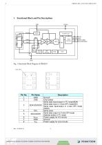
1 Functional Block and Pin Descriptions Competitive sensor & power supply solutions worldwide
Open the catalog to page 3
Competitive sensor & power supply solutions worldwide
Open the catalog to page 4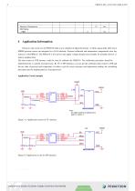
Owing to state of the art, the PBM210 build a new standard of digital barometer. A 24bits sigma-delta ADC and a MEMS pressure sensor are integrated in a LGA substrate. Pressure calibrated and temperature compensated were key features of the PBM210. The PBM210 is low power and supply voltage designed and suitable for portable devices or battery-supplied ones. The data stored in OTP memory could be used to calibrate the PBM210. The calibration procedure should be implemented by a external microprocessor. By I2C or SPI interface, you can get the calibration data stored in OTP and the raw data of...
Open the catalog to page 5
5 Control registers Table 5.1 control registers Reg 0xF6-0xF8 Data_out: 24 bits ADC output data Reg 0xF4 OSR<1:0>: 00:1024X, 01:2048X, 10:4096X, 11:8192X Measurement_control<5:0>: 101110, indicate a temperature conversion. 110100, indicate a pressure conversion. Reg 0xE0 Softreset : Write only register. If set to 0xB6, will perform a power on reset sequence. Auto returned to 0 after the soft reset completed. Reg {0xF1, 0xD0, 0xBB:0xAA} Calibration Registers : Total 20bytes calibration registers used for sensor calibration. Reg 0x6B PartID: 8 bits Part ID, the default value is 0x42. Reg 0x00 SDO_active:...
Open the catalog to page 6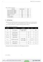
Table 5.2 Summary of instructions Competitive sensor & power supply solutions worldwide
Open the catalog to page 7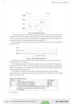
Figure 6.1 SPI timing diagram The falling edge of CSB, in conjunction with the rising edge of SCLK, determines the start of framing. Once the beginning of the frame has been determined, timing is straightforward. The first phase of the transfer is the instruction phase, which consists of 16 bits followed by data that can be of variable lengths in multiples of 8 bits. If the device is configured with CSB tied low, framing begins with the first rising edge of SCLK. The instruction phase is the first 16 bits transmitted. As shown in Figure 6.2, the instruction phase is divided into a number of bit...
Open the catalog to page 8
Data follows the instruction phase. The amount of data sent is determined by the word length (Bit W0 and Bit W1). This can be one or more bytes of data. All data is composed of 8-bit words. Data can be sent in either MSB-first mode or LSB-first mode (by setting ‘LSB_first’ bit). On power up, MSB-first mode is the default. This can be changed by programming the configuration register. In MSB-first mode, the serial exchange starts with the highest-order bit and ends with the LSB. In LSB-first mode, the order is reversed. (Figure 6.3) CSB \I SDIO DON'T CARE \ R/W W1 | W0 | A12 | A11 | A10 | A9...
Open the catalog to page 9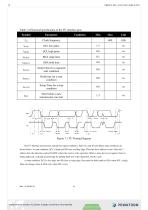
Table 7.2 Electrical specification of the I2C interface pins The I2C interface protocol has special bus signal conditions. Start (S), stop (P) and binary data conditions are shown below. At start condition, SCL is high and SDA has a falling edge. Then the slave address is sent. After the 7 address bits, the direction control bit R/W selects the read or write operation. When a slave device recognizes that it is being addressed, it should acknowledge by pulling SDA low in the ninth SCL (ACK) cycle. At stop condition, SCL is also high, but SDA has a rising edge. Data must be held stable at SDA when...
Open the catalog to page 10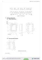
DATA ACK START ADDRESS R/W ACK condition DATA ACK STOP Competitive sensor & power supply solutions worldwide
Open the catalog to page 11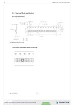
8.3.2 Sensor orientation relative to the tape Competitive sensor & power supply solutions worldwide
Open the catalog to page 12
Competitive sensor & power supply solutions worldwide
Open the catalog to page 13
Office Germany: Pewatron Deutschland GmbH EdisonstraEe 16 D-85716 UnterschleiEheim Phone +49 89 374 288 87-0 [email protected] PEWATRON 5ENS0R5 • POWER SOLUTIONS Geometrical sensors Sensor elements Thorsten Ravagni Phone +49 60 479 53 627 [email protected] Sales Other Countries / Product Management Pressure Sensors Gas sensors / Gas sensor modules Load cells Dr. Thomas Clausen Phone + 41 44 877 35 13 [email protected] Flow / Level / Medical products Linear position sensors Angle sensors Eric Letsch Phone + 41 44 877 35 14 [email protected] Accelerometers / Level...
Open the catalog to page 14All Angst+Pfister Sensors and Power AG catalogs and technical brochures
 SQ-UST_L_0105-01
4 Pages
 SQ-UST_L_0104-01
4 Pages
 SQ-UST_L_0103-01
4 Pages
 SQ-UST_L_0003-01
3 Pages
 SQ-UST_L_0002-01
3 Pages
 SQ-UST_L_0001-01
3 Pages
 PFLOW Series
5 Pages
 Model PFLOW3000 Series
16 Pages
 LoadSensor StarterKit
3 Pages
 Model PFLOW2001 Series
14 Pages
 PSB82_1685-21629-0010-E-1118
3 Pages
 PHPS5600 Pressure Transducer
6 Pages
 PEWA200 Pressure Transmitter
7 Pages
 PZA-MC25-N/P
2 Pages
 PEWA100
9 Pages
 HLP-80H series
5 Pages
 HLP-40H series
5 Pages
 HBG-60P series
6 Pages
 UHP-750 series
6 Pages
 XLG-50 seri es
9 Pages
 DAP-04 series
8 Pages
 POB-30 series
11 Pages
 RHP-1U Rack System
9 Pages
 RFP-M8M4-5A
5 Pages
 RFP-M5M3-3A
4 Pages
 RFP-M2M3-3A
4 Pages
 RFP-M1M3-3A
4 Pages
 NCL CL1 01
4 Pages
 IRL RGB 01
4 Pages
 IRL CL2 01
4 Pages
 MSR385WD
3 Pages
 MSR145WD
3 Pages
 MSR 145
3 Pages
 M2029
M20293 Pages
 MSR165
3 Pages
 CRM102.1
33 Pages
 CRM200
39 Pages
 CRM100
37 Pages
 FPM
FPM4 Pages
 FGN
FGN4 Pages
 FPN
FPN4 Pages
 PBM220-A14N series
14 Pages
 PBM220 series
15 Pages
 STX Series – Model 13A
11 Pages
 CCD Series – Model 53A
7 Pages
 CCD Series – Model 54D
20 Pages
 APB2Series
5 Pages
 AP4Series
5 Pages
 AP2Series
5 Pages
 PHPS-7500 OEM
6 Pages
 PPCP3-M1
10 Pages
 AG4Series
6 Pages
 AG2Series
5 Pages
 New Pewatron brochure
11 Pages
 GST220A
4 Pages
 GSM40B
6 Pages
 GSM36B
4 Pages
 GSC25E
5 Pages
 TDR-480
5 Pages
 GC120
GC1204 Pages
 HDR-30
5 Pages
 GSM220A
6 Pages
 EPP-400
5 Pages
 ENP-120
5 Pages
 ENC-120
6 Pages
 ATX-100
4 Pages
 RPS-200
7 Pages
 APBR30X75
2 Pages
 APBR30X60
2 Pages
 APBR 30X50 MM
2 Pages
 PSB54/16
2 Pages
 PSB54/14
2 Pages
 PSB36T/16
2 Pages
 PSB35T/12
2 Pages
 PSB25T/16
2 Pages
 PSB25T/12
2 Pages
 PSB21/12
2 Pages
 PSB 21
2 Pages
 AD-Series
16 Pages
 DMU11
DMU113 Pages
 HDR-30 series
5 Pages
 DMU30-01
25 Pages
 DMU30
DMU303 Pages
 DKA30 serie s
2 Pages
 DCW12
DCW122 Pages
 DCW05
DCW052 Pages
 EH - EF 80 C/P/K
3 Pages
 7S Series
3 Pages
 Model CE36M
3 Pages
 EX 80 A
3 Pages
 STX13A-D_100-31-410-005-EH-0817
11 Pages
 PBM220_100-33-421-003-EH-1216
16 Pages
 ABS5_100-33-102-001-EH-1016
2 Pages
 PHPS-8500_100-31-331-003-EH-0617
12 Pages
 100 33 102 012 EH 0315
6 Pages
 100 33 102 007 EH 0315
5 Pages
 UFO
UFO3 Pages
 UFO-M2
3 Pages
 Dummy DC-Motoren
2 Pages
 FCX-MP1000-Extern-FH-CH
3 Pages
 GC30E
GC30E3 Pages
 RPS-400
11 Pages
 GC 330
4 Pages
 EL30
EL303 Pages
 EA PROFIBUS
7 Pages
 EAMW
EAMW3 Pages
 AAM58
AAM584 Pages
 EAM36
EAM363 Pages
 CARBONOXY25
2 Pages
 CARBONDIO-%
2 Pages
 FCX-ML25-EXTERN-CH
14 Pages
 FCX-MC25-CH
3 Pages
 FCX-MC05-CH
3 Pages
 FCX-TR0025
4 Pages
 LP-10HA
3 Pages
 FCX-UC-CH
9 Pages
 901.1-EX
5 Pages
 FC22
FC223 Pages
 MILLINEWTON
3 Pages
 PFLOW10U-2210
5 Pages
 901.1
901.15 Pages
 HX-EP
HX-EP6 Pages
 VQ548MP & MP-7217
5 Pages
 Air quality sensing
6 Pages
 Tailor-made
10 Pages
 RAZTEC
13 Pages
 The SGX-SureCO
3 Pages
 930 Climair
5 Pages
 984 pressure transmitter
5 Pages
 PEM pressure transmitter
5 Pages
 Pressure sensor CCD54
4 Pages
 MSP-600 600W AC/DC
5 Pages
 FCX-MP1000-Extern-FH-CH
3 Pages
 Pewatron_Flyer_EN
8 Pages


- Electromotor
- Flowmeter
- DC electromotor
- Synchronous motor
- Angst + Pfister temperature sensor
- Liquid flow monitor
- Angst + Pfister gas analyzer
- Multipole motor
- Concentration analyzer
- Angular encoder
- Resistance temperature sensor
- Angst + Pfister pressure transmitter
- Tension/compression force transducer
- Electromotor for industrial applications
- EC motor
- Incremental encoder
- 24 V motor
- Angst + Pfister analog pressure transmitter
- Gas flow monitor