- Catalogs
- Angst+Pfister Sensors and Power AG
- OEM Mass Flow Controller PFLOW5001 / PFLOWC5001
- Company
- Products
- Catalogs
- News & Trends
- Exhibitions
OEM Mass Flow Controller PFLOW5001 / PFLOWC5001
1 /39Pages

OEM Mass Flow Controller PFLOW5001 / PFLOWC5001
1 /39Pages
Catalog excerpts

OEM Mass Flow ControllerModel PFLOW5001 / PFLOWC5001 Experts on Design-In Wl d Angst+Pfister Sensors and Power
Open the catalog to page 1
/j\ Attention! • Please carefully read this manual prior to operating this product. • Do not open or modify any hardware which may lead to irrecoverable damage. • Do not use this product if you suspect any malfunctions or defection. • Do not use this product for corrosive media or in a strong vibration environment. • Use this product according to the specified parameters. • Only the trained or qualified personnel shall be allowed to perform product services. Use with caution! • Be cautious for electrical safety, and even it operates at a low voltage, any electrical shock might lead to some unexpected...
Open the catalog to page 2
1. Overview This manual provides essential information for the operation of the PFLOW5001 / PFLOWC5001 series of gas mass flow sensors for general-purpose gas flow monitor and control applications with the full-scale mass flow rate from 0.2 to 20 SLPM, and both analog and digital outputs. The product performance, maintenance, and troubleshooting as well as the information for product order, technical support, and repair are also included. PFLOW5001 / PFLOWC5001 are available in the manifold configuration for the mechanical connections. Optionally they can also be offered with a manifold body...
Open the catalog to page 5
2. Receipt / unpack of the products Upon receipt of the products, please check the packing box before dismantling the packing materials. Ensure no damages during shipping. If any abnormality is observed, please contact and notify the carrier who shipped the product and inform the distributors or sales representatives if the order is not placed directly with the manufacturer; otherwise, the manufacturer should be informed. Please refer to the return and repair section in this manual for any further actions. If the packing box is intact, proceed to open the packing box, and you shall find the product...
Open the catalog to page 6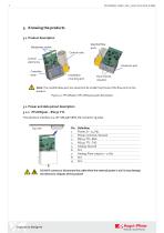
Data/power socket Control electronics Controller body Control valve Installation mounting port. Manifold flow ports Flow channel in/outlet Note: The manifold base port size should not be smaller than those of the flow ports on the product. Figure 3.1: PFLOW5001 / PFLOWC5001 parts description 3.2 Power and data pinout description 3.2.1 PFLOW5001 - RS232 TTL The electrical interface is a JST-SM09B-SRSS-TB connector (9 pole). Pin Definition 1 P ower, 8 ~ 2 4 Vdc 2 Power common / Ground 3 R S 2 3 2 TT L : Rx D 6 N.C. 7 Analog: Flow output 0 ~ 5 Vdc 8 N.C. 9 N.C. DO NOT connect or disconnect the cable...
Open the catalog to page 7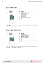
3.2.2 PFLOW5001 - RS232 EIA The electrical interface is a Micromatch (8 pole). 6 Analog: Flow output 0 ~ 5 Vdc AA DO NOT connect or disconnect the cable when the external power is on!! It may damage the electronic chipsets of the product! 3.2.3 PFLOW5001 - RS485 Half-duplex The electrical interface is a Micromatch (8 pole). VoV Pin Defi n ition 1 Power, 8 ~ 24 Vdc 2 Powe r co m m on / G ro un d DO NOT connect or disconnect the cable when the external power is on!! It may damage the electronic chipsets of the product! Wl d Angst+Pfister Sensors and Power
Open the catalog to page 8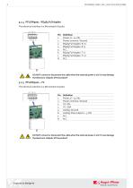
3.2.4 PFLOW5001 - RS485 Full-duplex The electrical interface is a Micromatch (8 pole). Wt Pin Defi n ition 1 Power, 8 ~ 24 Vdc AA DO NOT connect or disconnect the cable when the external power is on!! It may damage the electronic chipsets of the product! 3.2.5 PFLOW5001 - I2C The electrical interface is a Micromatch (8 pole). 6 Analog: Flow output 0 ~ 5 Vdc DO NOT connect or disconnect the cable when the external power is on!! It may damage the electronic chipsets of the product! Wl d Angst+Pfister Sensors and Power
Open the catalog to page 9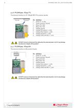
The electrical interface is a JST-SM09B-SRSS-TB connector (9 pole). 2 Power common / Ground 3 RS232TTL : RxD 7 Analog: Flow output 0 ~ 5 Vdc 8 Analog: Set point 0 ~ 5 Vdc 9 Analog: Valve override 0 ~ 5 Vdc DO NOT connect or disconnect the cable when the external power is on!! It may damage the electronic chipsets of the product! The electrical interface is a Micromatch (8 pole). 6 Analog: Flow output 0 ~ 5 Vdc 7 Analog: Set point 0 ~ 5 Vdc 8 Analog: Valve override 0 ~ 5 Vdc DO NOT connect or disconnect the cable when the external power is on!! It may damage the electronic chipsets of the product!...
Open the catalog to page 10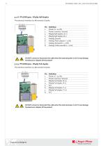
The electrical interface is a Micromatch (8 pole). Pin Defi n ition 1 Power, 8 ~ 24 Vdc 6 Analog: Flow output 0 ~ 5 Vdc 7 Analog: Set point 0 ~ 5 Vdc 8 Analog: Valve override 0 ~ 5 Vdc AA DO NOT connect or disconnect the cable when the external power is on!! It may damage the electronic chipsets of the product! 3.2.9 PFLOWC5001 - RS485 Full-duplex The electrical interface is a Micromatch (8 pole). Pin Defi n ition 1 Power, 8 ~ 24 Vdc DO NOT connect or disconnect the cable when the external power is on!! It may damage the electronic chipsets of the product! Wl d Angst+Pfister Sensors and Power
Open the catalog to page 11
Note: 1. Power supply: The PFLOW5001 / PFLOWC5001 requires a power supply of 8 ~ 24 Vdc (max 26 Vdc). No particular requirements for the external power supply, but standard industrial power cautions should be applied. 2. The analog outputs 0 ~ 5 Vdc correspond to the specified full-scale flow range at the time of order. If the analog option is not selected, this pin output could be NULL. 3. For PFLOWC5001 - RS232 TTL, RS232 EIA and RS485 Half-duplex, the analog valve override feature overrules all other commands. The thresholds of valve override is 0.2Vdc. 0.0 ~ 0.2 Vdc: valve close 4.8 ~ 5.0...
Open the catalog to page 12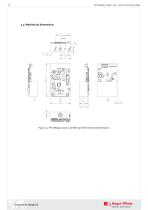
Figure 3.2: PFLOW5001 (up to 3 SLPM) manifold mechanical dimensions.
Open the catalog to page 13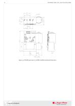
Figure 3.3: PFLOWC5001 (up to 7.5 SLPM) manifold mechanical dimensions.
Open the catalog to page 14
4. Installation Do not open or alter any part of the product, which would lead to malfunction and irrecoverable damage. Please pay special attention to ESD and other electrical device handling precautions since this unit is an OEM version without external protection of the PCB etc. The system design should consider electromagnetic compatibility and related standards. Do not install this device for processes involving personal injury or other unsafe applications. Ensure the connections leakage proof and all electrical precautions are applied for the installation. Please make sure the electrical...
Open the catalog to page 15All Angst+Pfister Sensors and Power AG catalogs and technical brochures
 SQ-UST_L_0105-01
4 Pages
 SQ-UST_L_0104-01
4 Pages
 SQ-UST_L_0103-01
4 Pages
 SQ-UST_L_0003-01
3 Pages
 SQ-UST_L_0002-01
3 Pages
 SQ-UST_L_0001-01
3 Pages
 PFLOW Series
5 Pages
 Model PFLOW3000 Series
16 Pages
 LoadSensor StarterKit
3 Pages
 Model PFLOW2001 Series
14 Pages
 PSB82_1685-21629-0010-E-1118
3 Pages
 PHPS5600 Pressure Transducer
6 Pages
 PEWA200 Pressure Transmitter
7 Pages
 PZA-MC25-N/P
2 Pages
 PEWA100
9 Pages
 HLP-80H series
5 Pages
 HLP-40H series
5 Pages
 HBG-60P series
6 Pages
 UHP-750 series
6 Pages
 XLG-50 seri es
9 Pages
 DAP-04 series
8 Pages
 POB-30 series
11 Pages
 RHP-1U Rack System
9 Pages
 RFP-M8M4-5A
5 Pages
 RFP-M5M3-3A
4 Pages
 RFP-M2M3-3A
4 Pages
 RFP-M1M3-3A
4 Pages
 NCL CL1 01
4 Pages
 IRL RGB 01
4 Pages
 IRL CL2 01
4 Pages
 MSR385WD
3 Pages
 MSR145WD
3 Pages
 MSR 145
3 Pages
 M2029
M20293 Pages
 MSR165
3 Pages
 CRM102.1
33 Pages
 CRM200
39 Pages
 CRM100
37 Pages
 FPM
FPM4 Pages
 FGN
FGN4 Pages
 FPN
FPN4 Pages
 PBM220-A14N series
14 Pages
 PBM220 series
15 Pages
 PBM210-A20K Series
14 Pages
 STX Series – Model 13A
11 Pages
 CCD Series – Model 53A
7 Pages
 CCD Series – Model 54D
20 Pages
 APB2Series
5 Pages
 AP4Series
5 Pages
 AP2Series
5 Pages
 PHPS-7500 OEM
6 Pages
 PPCP3-M1
10 Pages
 AG4Series
6 Pages
 AG2Series
5 Pages
 New Pewatron brochure
11 Pages
 GST220A
4 Pages
 GSM40B
6 Pages
 GSM36B
4 Pages
 GSC25E
5 Pages
 TDR-480
5 Pages
 GC120
GC1204 Pages
 HDR-30
5 Pages
 GSM220A
6 Pages
 EPP-400
5 Pages
 ENP-120
5 Pages
 ENC-120
6 Pages
 ATX-100
4 Pages
 RPS-200
7 Pages
 APBR30X75
2 Pages
 APBR30X60
2 Pages
 APBR 30X50 MM
2 Pages
 PSB54/16
2 Pages
 PSB54/14
2 Pages
 PSB36T/16
2 Pages
 PSB35T/12
2 Pages
 PSB25T/16
2 Pages
 PSB25T/12
2 Pages
 PSB21/12
2 Pages
 PSB 21
2 Pages
 AD-Series
16 Pages
 DMU11
DMU113 Pages
 HDR-30 series
5 Pages
 DMU30-01
25 Pages
 DMU30
DMU303 Pages
 DKA30 serie s
2 Pages
 DCW12
DCW122 Pages
 DCW05
DCW052 Pages
 EH - EF 80 C/P/K
3 Pages
 7S Series
3 Pages
 Model CE36M
3 Pages
 EX 80 A
3 Pages
 STX13A-D_100-31-410-005-EH-0817
11 Pages
 PBM220_100-33-421-003-EH-1216
16 Pages
 ABS5_100-33-102-001-EH-1016
2 Pages
 PHPS-8500_100-31-331-003-EH-0617
12 Pages
 100 33 102 012 EH 0315
6 Pages
 100 33 102 007 EH 0315
5 Pages
 UFO
UFO3 Pages
 UFO-M2
3 Pages
 Dummy DC-Motoren
2 Pages
 FCX-MP1000-Extern-FH-CH
3 Pages
 GC30E
GC30E3 Pages
 RPS-400
11 Pages
 GC 330
4 Pages
 EL30
EL303 Pages
 EA PROFIBUS
7 Pages
 EAMW
EAMW3 Pages
 AAM58
AAM584 Pages
 EAM36
EAM363 Pages
 CARBONOXY25
2 Pages
 CARBONDIO-%
2 Pages
 FCX-ML25-EXTERN-CH
14 Pages
 FCX-MC25-CH
3 Pages
 FCX-MC05-CH
3 Pages
 FCX-TR0025
4 Pages
 LP-10HA
3 Pages
 FCX-UC-CH
9 Pages
 901.1-EX
5 Pages
 FC22
FC223 Pages
 MILLINEWTON
3 Pages
 PFLOW10U-2210
5 Pages
 901.1
901.15 Pages
 HX-EP
HX-EP6 Pages
 VQ548MP & MP-7217
5 Pages
 Air quality sensing
6 Pages
 Tailor-made
10 Pages
 RAZTEC
13 Pages
 The SGX-SureCO
3 Pages
 930 Climair
5 Pages
 984 pressure transmitter
5 Pages
 PEM pressure transmitter
5 Pages
 Pressure sensor CCD54
4 Pages
 MSP-600 600W AC/DC
5 Pages
 FCX-MP1000-Extern-FH-CH
3 Pages
 Pewatron_Flyer_EN
8 Pages


- Electromotor
- Challenge Power Transmission flow meter
- DC electromotor
- Synchronous motor
- Challenge Power Transmission temperature sensor
- Challenge Power Transmission liquid flow meter
- Force sensor
- Challenge Power Transmission gas analyzer
- Multipole motor
- Angular encoder
- Challenge Power Transmission concentration analyzer
- Challenge Power Transmission resistance temperature sensor
- Challenge Power Transmission pressure transmitter
- Tension/compression force transducer
- Electromotor for industrial applications
- Incremental encoder
- EC motor
- Challenge Power Transmission analog pressure transmitter
- 24 V motor
- Gas flow monitor