- Catalogs
- Angst+Pfister Sensors and Power AG
- Model PFLOW3000 Series
- Company
- Products
- Catalogs
- News & Trends
- Exhibitions
Model PFLOW3000 Series
1 /16Pages

Model PFLOW3000 Series
1 /16Pages
Catalog excerpts
Model PFLOW3000 Series MEMS Mass Flow Sensors (VA.0)
Open the catalog to page 1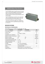
MEMS Mass Flow Sensor The PFLOW3000 series of mass flow sensors are made with the micromachined (MEMS) sensing elements that ` offer an innovative thermal sensing principle with excellent linearity and removal of gas sensitivity of some common gases. This PFLOW3000 Series mass flow sensor series offer a fully customizable flow dynamic range of 100:1 with the full-scale flowrate from 2 SLPM to 50 SLPM. The sensors are opted with digital (I2C or RS485) and analog interface, with an operational temperature range of -10 to 55 °C. SPECIFICATIONS Performance characteristics (Test conditions: Vcc =...
Open the catalog to page 2
Electrical Characteristics (Test conditions: Vcc = 8-15VDC, Ta = 20°C, RHa = 30…70%) Item Supply voltage Supply current Warmup time (4) Minimum Output load (analog & digital version) Response time (digital, analog) Output (analog) (5) Analog null voltage Analog null drift Maximum output (6) Output (digital) I2C bus voltage I2C frequency Resolution digital output Digital null offset Digital null drift (7) Note: 1. SLPM denotes standard cubic centimeters per minute. Standard conditions: 20°C, 101.325kPa, dry and clean air. 2. Accuracy is the combined error from offset and span calibration, linearity,...
Open the catalog to page 3
PRESSURE DROP CHARACTERISTICS The product is designed for low-pressure loss. The major drop in the pressure is at the manual valve structure. The following graph illustrated the pressure losses of the selected models. Table 1: PFLOW3003 pressure loss Flow rate (SLPM) Table 2: PFLOW3008 pressure loss Flow rate (SLPM)
Open the catalog to page 4
MECHANICAL DIMENSIONS Figure 3: PFLOW3000 dimensions with BSPT (R1/4”) connectors. All units are in mm Figure 4: PFLOW3000 dimensions with one-touch connectors. All units are in mm
Open the catalog to page 5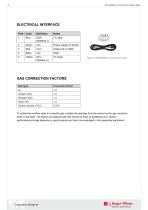
Figure 5: PFLOW3000 connection and cable GAS CORRECTION FACTORS Gas type Correction factor To obtain the real flow rates in a specific gas, multiply the readings from the sensor by the gas correction factor in the table. The factors are approximate and should be used as guidelines only. Sensor performance strongly depends on gas dynamics and has to be evaluated in the respective application.
Open the catalog to page 6
TYPICAL OUTPUT (ANALOG OUTPUT) Analog Output Table 3: PFLOW3000 typical analog output Flow rate (SLPM) Typical Analog output (Vdc) 4.9 Figure 6: PFLOW3000 typical analog output Digital Output Table 4: PFLOW3000 typical digital output Flow rate (SLPM) Typical Digital output (SLPM) 1.1FS Figure 7: PFLOW3000 typical digital output
Open the catalog to page 7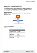
DIGITAL RS485 Modbus COMMUNICATION The digital communication protocol is based on standard Modbus RTU Half-plex mode. A master (PC or PLC) can communicate with multiple slaves (the current product) for data exchange and communication parameter configuration. Refer to ELECTRICAL INTERFACE for cable connection. Hardware connection The RS485 hardware layer is TIA/EIA-485-A, as illustrated below. In this configuration, the product (PFLOW3000) is a slave. Communication parameters The PC UART communication parameters are listed in the following table. Parameters Baud rate (Bits per second) Start bits...
Open the catalog to page 8
Frame The frame function is based on the standard Modbus RTU framing: Start_bits T1-T2-T3-T4 4 periods bit time, for a new frame. The address can be set from 1 to 247 except for 157 (0x9d). 0 is the broadcast address. Function codes: Define the product's functions/actions (slaves), either execution or response. The address of the register, length of data, and the data themselves. CRC verification code. The low byte is followed by the high byte. For example, a 16-bit CRC is divided into BYTE_H and BYTE_L. In the framing, the BYTE_L will come first, then followed by the BYTE_H. The last one is...
Open the catalog to page 9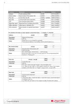
Serial number Serial number of the product (R) Flow rate Current flow rate (R) Baud rate Communication baud rate (R/W) Digital filter depth Response time or sampling time (R/W) Offset calibration Offset reset or calibration (W) Write protection Write protection of selected parameters (W) The detailed information of each register is described below: Y: enabled; N: disabled Write Y Address 0x0081 Read Y Description Address of the product Value type UINT 16 Values from 1 to 247 except for 157 (0x9d). Notes The broadcast address is not enabled, and the default address is 1. SN, Serial number Description...
Open the catalog to page 10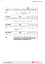
GCF Description Value type Notes Response time Description Value type Notes Offset calibration Description Value type Notes Write protection Description Value type Write Y Read Y The gas conversion factor for applicable gas is different from calibration gas UINT 16 The GCF of air is 1000 (default), normally read from register 0x008B. Note: The product will disable this function with write protection once the metering gas is confirmed with the proper GCF. For a specific GCF value, please contact the manufacturer. 0x008B Write Read Digital filter depth setting UINT 16 0 ~ 9 programmable, corresponding...
Open the catalog to page 11
DIGITAL I2C COMMUNICATION I2C interface connection diagram I2C interface command description Command Width (Byte) Command Name Filter depth Reset the offset of differential pressure Sensor serial number Flow rate Gas correction factor (GCF) Notes Int 16. bit 0 is the R/W flag bit; bit 1 ~ bit 7 are available; bit 8 ~ bit 15 = 0. The default I2C address is 1. Hex: 0x0002 (write) /0x0003 (read), Bin: 0000 0000 0000 0010 (write) 0000 0000 0000 0011 (read). Int 32/1000 SLPM The gas conversion factor for applicable gas is different from calibration gas. Int 16, 0 ~ 9, corresponding to 20 ~ 29 data...
Open the catalog to page 12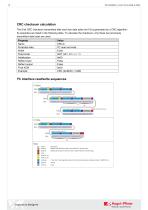
CRC checksum calculation The 8-bit CRC checksum transmitted after each two data bytes (int 16) is generated by a CRC algorithm. Its properties are listed in the following table. To calculate the checksum, only these two previously transmitted data bytes are used. Property Name Protected data Width Polynomial Initialization Reflect input Reflect output Final XOR Example Value CRC-8 I2C read and write 8 bits 0x07 (x8 + x2 + x + 1) 0x00 False False 0x00 CRC (0x4E20) = 0x6D I2C interface read/write sequences
Open the catalog to page 13All Angst+Pfister Sensors and Power AG catalogs and technical brochures
 SQ-UST_L_0105-01
4 Pages
 SQ-UST_L_0104-01
4 Pages
 SQ-UST_L_0103-01
4 Pages
 SQ-UST_L_0003-01
3 Pages
 SQ-UST_L_0002-01
3 Pages
 SQ-UST_L_0001-01
3 Pages
 PFLOW Series
5 Pages
 LoadSensor StarterKit
3 Pages
 Model PFLOW2001 Series
14 Pages
 PSB82_1685-21629-0010-E-1118
3 Pages
 PHPS5600 Pressure Transducer
6 Pages
 PEWA200 Pressure Transmitter
7 Pages
 PZA-MC25-N/P
2 Pages
 PEWA100
9 Pages
 HLP-80H series
5 Pages
 HLP-40H series
5 Pages
 HBG-60P series
6 Pages
 UHP-750 series
6 Pages
 XLG-50 seri es
9 Pages
 DAP-04 series
8 Pages
 POB-30 series
11 Pages
 RHP-1U Rack System
9 Pages
 RFP-M8M4-5A
5 Pages
 RFP-M5M3-3A
4 Pages
 RFP-M2M3-3A
4 Pages
 RFP-M1M3-3A
4 Pages
 NCL CL1 01
4 Pages
 IRL RGB 01
4 Pages
 IRL CL2 01
4 Pages
 MSR385WD
3 Pages
 MSR145WD
3 Pages
 MSR 145
3 Pages
 M2029
M20293 Pages
 MSR165
3 Pages
 CRM102.1
33 Pages
 CRM200
39 Pages
 CRM100
37 Pages
 FPM
FPM4 Pages
 FGN
FGN4 Pages
 FPN
FPN4 Pages
 PBM220-A14N series
14 Pages
 PBM220 series
15 Pages
 PBM210-A20K Series
14 Pages
 STX Series – Model 13A
11 Pages
 CCD Series – Model 53A
7 Pages
 CCD Series – Model 54D
20 Pages
 APB2Series
5 Pages
 AP4Series
5 Pages
 AP2Series
5 Pages
 PHPS-7500 OEM
6 Pages
 PPCP3-M1
10 Pages
 AG4Series
6 Pages
 AG2Series
5 Pages
 New Pewatron brochure
11 Pages
 GST220A
4 Pages
 GSM40B
6 Pages
 GSM36B
4 Pages
 GSC25E
5 Pages
 TDR-480
5 Pages
 GC120
GC1204 Pages
 HDR-30
5 Pages
 GSM220A
6 Pages
 EPP-400
5 Pages
 ENP-120
5 Pages
 ENC-120
6 Pages
 ATX-100
4 Pages
 RPS-200
7 Pages
 APBR30X75
2 Pages
 APBR30X60
2 Pages
 APBR 30X50 MM
2 Pages
 PSB54/16
2 Pages
 PSB54/14
2 Pages
 PSB36T/16
2 Pages
 PSB35T/12
2 Pages
 PSB25T/16
2 Pages
 PSB25T/12
2 Pages
 PSB21/12
2 Pages
 PSB 21
2 Pages
 AD-Series
16 Pages
 DMU11
DMU113 Pages
 HDR-30 series
5 Pages
 DMU30-01
25 Pages
 DMU30
DMU303 Pages
 DKA30 serie s
2 Pages
 DCW12
DCW122 Pages
 DCW05
DCW052 Pages
 EH - EF 80 C/P/K
3 Pages
 7S Series
3 Pages
 Model CE36M
3 Pages
 EX 80 A
3 Pages
 STX13A-D_100-31-410-005-EH-0817
11 Pages
 PBM220_100-33-421-003-EH-1216
16 Pages
 ABS5_100-33-102-001-EH-1016
2 Pages
 PHPS-8500_100-31-331-003-EH-0617
12 Pages
 100 33 102 012 EH 0315
6 Pages
 100 33 102 007 EH 0315
5 Pages
 UFO
UFO3 Pages
 UFO-M2
3 Pages
 Dummy DC-Motoren
2 Pages
 FCX-MP1000-Extern-FH-CH
3 Pages
 GC30E
GC30E3 Pages
 RPS-400
11 Pages
 GC 330
4 Pages
 EL30
EL303 Pages
 EA PROFIBUS
7 Pages
 EAMW
EAMW3 Pages
 AAM58
AAM584 Pages
 EAM36
EAM363 Pages
 CARBONOXY25
2 Pages
 CARBONDIO-%
2 Pages
 FCX-ML25-EXTERN-CH
14 Pages
 FCX-MC25-CH
3 Pages
 FCX-MC05-CH
3 Pages
 FCX-TR0025
4 Pages
 LP-10HA
3 Pages
 FCX-UC-CH
9 Pages
 901.1-EX
5 Pages
 FC22
FC223 Pages
 MILLINEWTON
3 Pages
 PFLOW10U-2210
5 Pages
 901.1
901.15 Pages
 HX-EP
HX-EP6 Pages
 VQ548MP & MP-7217
5 Pages
 Air quality sensing
6 Pages
 Tailor-made
10 Pages
 RAZTEC
13 Pages
 The SGX-SureCO
3 Pages
 930 Climair
5 Pages
 984 pressure transmitter
5 Pages
 PEM pressure transmitter
5 Pages
 Pressure sensor CCD54
4 Pages
 MSP-600 600W AC/DC
5 Pages
 FCX-MP1000-Extern-FH-CH
3 Pages
 Pewatron_Flyer_EN
8 Pages


- Electromotor
- Challenge Power Transmission flow meter
- DC electromotor
- Synchronous motor
- Challenge Power Transmission temperature sensor
- Challenge Power Transmission liquid flow meter
- Force sensor
- Challenge Power Transmission gas analyzer
- Multipole motor
- Angular encoder
- Challenge Power Transmission concentration analyzer
- Challenge Power Transmission resistance temperature sensor
- Challenge Power Transmission pressure transmitter
- Tension/compression force transducer
- Electromotor for industrial applications
- Incremental encoder
- EC motor
- Challenge Power Transmission analog pressure transmitter
- 24 V motor
- Gas flow monitor