- Catalogs
- Angst+Pfister Sensors and Power AG
- FCX-ML25-EXTERN-CH
- Company
- Products
- Catalogs
- News & Trends
- Exhibitions
FCX-ML25-EXTERN-CH
1 /14Pages

FCX-ML25-EXTERN-CH
1 /14Pages
Catalog excerpts

Operating manualOxygen sensor module FCX-MLxx-CH & FCX-MLxx-Extern -CH Competitive sensor & power supply solutions worldwide
Open the catalog to page 1
This manual contain information on how to operate the standard Pewatron OEM FCX-MLxx-CH and FCX-MLxx-Extern-CH products. The standard FCX-MLxx-CH configuration always have the oxygen sensor soldered onto the PCB and covered with an aluminium flow housing. The standard FCX-MLxx-Extern-CH configuration have the oxygen sensor connected to the PCB via a 30 cm long cable. The oxygen sensor can be chosen from a selection of 3 sensors; 3) the FCX-UWC 0.1.95% (xx = 95) As an example the FCX-ML95-CH Module is a 0.1-95% FCX-UWC oxygen sensor module used in flow applications or in applications where a gas...
Open the catalog to page 2
1 List of Contents Page 1. Safety instructions
Open the catalog to page 3
2 Customer Service At PEWATRON AG, we want to offer you the best customer service possible. If you have any questions or comments about your FCX-MLxx-CH or FCX-MLxx-Extern-CH modules, we would be happy to hear from you. Should you have any problems with the modules, please contact us for advice and support. We recommend that all service and repair work on the unit be done exclusively by our customer service or specially trained personnel. You can reach us at the following addresses: Headquarter: PEWATRON AG Thurgauerstrasse 66 8052 Zurich Switzerland Tel +41 (0)44-877 35 00 Fax +41 (0)44-877...
Open the catalog to page 4
3 Safety instructions Danger sources that could result in personal injury or damage to machinery are explicitly indicated in the appropriate places in the user documentation. Before installing the machine, please read this operating manual carefully. Pay particular attention to the sections explaining possible hazards. Warnings and instructions are shown as follows: A Means that failure to follow the instruction indicated can lead to personal injury. Means that the instruction indicated must be followed exactly to prevent damage to the machine. Competitive sensor & power supply solutions worldwide...
Open the catalog to page 5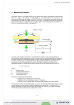
4 Measuring Principle The sensor module is a complete solution for fast and accurate oxygen concentration measurements within the range 0...5% (ML05), 0...25% (ML25) or 0.1...95% (ML95). The sensor and the measurement electronics are located on a PCB (FCX-MLxx-CH). Alternatively, the oxygen sensor can be connected to the PCB via a cable (FCX-MLxx-extern-CH). The electronic amplifies the raw sensor signal and the output is a logarithmic current output signal 4.20mA (according to IEC 60381) as a function of oxygen partial pressure (see Appendix) Zirconium oxide, heated to about 450 °C, is penetrable...
Open the catalog to page 6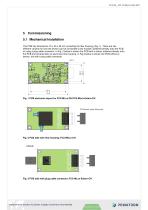
5 Commissioning 5.1 Mechanical Installation The PCB has dimensions 75 x 40 x 28 mm (including the flow housing) (Fig.1.). There are two different variants for how the sensor can be connected to the module: Soldered directly onto the PCB or using a plug cable connector. In Fig. 2 below is shown the PCB with a sensor soldered directly onto the PCB and covered with an aluminium flow housing. In Fig.3 below is shown the PCB without a sensor, but with a plug cable connector. Fig. 1 PCB electronic layout for FCX-MLxx-CH/FCX-MLxx-Extern-CH Fig. 2 PCB side with flow housing; FCX-MCxx-CH Fig. 3 PCB side...
Open the catalog to page 7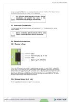
In each corner of the PCB, there are mounting holes with a diameter of 3.5 mm. The distance between the centre of mounting holes are 67 and 32 mm, respectively. A The PCB has highly sensitive circuitry. During installation, be careful that none of the caution components are damaged mechanically. 5.2 Pneumatic connections The flow housing has two hose connectors with a diameter of 5 mm. The direction of flow can be chosen arbitrarily. A Hoses containing silicone should not be used. Gases containing silicon destroy the sensor Caution cr GND Stromausgang (4..20 mA) GND Speisung (10..28 VDC) a The...
Open the catalog to page 8
6 Environment Condition See also under 11. Specifications, in particular for the temperature and humidity ranges (not condensing). • Operation outdoors not permitted. • Protect from moisture The sensor temperature is about 450 °C. Please note in any case the resulting hazards for applications with reactive gas mixtures. Potentially explosive atmospheres The unit may under no circumstances be operated in or with potentially explosive atmospheres. 7 Warm Up Time The module need a warm up time of approx. 3 minutes. After 3 minutes the sensor delivers an output signal which is within the accuracy...
Open the catalog to page 9
9.1 Calibration Adjustments It is recommended to check the device periodically by running it under regular lab conditions and flush the sensor with regular air (20.95% O2). 9.2 Adjustment Span and Zero Initial calibration of the ML module needed for operation has been carried out at the factory. The result of a measurement in air and at a temperature of 25°C should be 20.95 %O2 +0.2/-0.5% O2. Should there be a higher difference the module output can be adjusted according to the following procedure: 1 Attach the module to the supply 2 Use the sensor in regular air (20.95% O2). For the 0...5% sensor...
Open the catalog to page 10
9.3 Adjustment if the sensor need to be replaced 1. Attach the module to the supply 2. After approx. 10 minutes adjust the sensor heating (U Heat) using the potentiometer (Heizspannung) and jumpers S1 and S2 for fine adjusting (see jumper configuration below). Please note that the VH differs from sensor to sensor and has to be adjusted at an accuracy of +0.005V. The corresponding values can be found on the attached calibration sheet. open open close open open dose close close 3. Use the sensor in regular air (20.9% O2). For the 0...5% sensor please use a N2-O2 gas with an oxygen concentration...
Open the catalog to page 11
10 Important notes 10.1 Restrictions 1 Do not remove the sensor from the circuit board. 2 Do not change the length of the lead wires. 3 Please use regulated DC power source with current capacity over 1 ampere/pc. If current capacity is not sufficient, the sensor module will not operate correctly. 4 This sensor module was adjusted for O2-N2 system. Output characteristics may change if there are other gases present in the gas mixture to be measured. 5 Don't use in a gas that contains the halogen atoms (F, Cl, Br). The sensor can be damaged by decomposition of a gas containing halogen atoms. 6 SOx,...
Open the catalog to page 12All Angst+Pfister Sensors and Power AG catalogs and technical brochures
 SQ-UST_L_0105-01
4 Pages
 SQ-UST_L_0104-01
4 Pages
 SQ-UST_L_0103-01
4 Pages
 SQ-UST_L_0003-01
3 Pages
 SQ-UST_L_0002-01
3 Pages
 SQ-UST_L_0001-01
3 Pages
 PFLOW Series
5 Pages
 Model PFLOW3000 Series
16 Pages
 LoadSensor StarterKit
3 Pages
 Model PFLOW2001 Series
14 Pages
 PSB82_1685-21629-0010-E-1118
3 Pages
 PHPS5600 Pressure Transducer
6 Pages
 PEWA200 Pressure Transmitter
7 Pages
 PZA-MC25-N/P
2 Pages
 PEWA100
9 Pages
 HLP-80H series
5 Pages
 HLP-40H series
5 Pages
 HBG-60P series
6 Pages
 UHP-750 series
6 Pages
 XLG-50 seri es
9 Pages
 DAP-04 series
8 Pages
 POB-30 series
11 Pages
 RHP-1U Rack System
9 Pages
 RFP-M8M4-5A
5 Pages
 RFP-M5M3-3A
4 Pages
 RFP-M2M3-3A
4 Pages
 RFP-M1M3-3A
4 Pages
 NCL CL1 01
4 Pages
 IRL RGB 01
4 Pages
 IRL CL2 01
4 Pages
 MSR385WD
3 Pages
 MSR145WD
3 Pages
 MSR 145
3 Pages
 M2029
M20293 Pages
 MSR165
3 Pages
 CRM102.1
33 Pages
 CRM200
39 Pages
 CRM100
37 Pages
 FPM
FPM4 Pages
 FGN
FGN4 Pages
 FPN
FPN4 Pages
 PBM220-A14N series
14 Pages
 PBM220 series
15 Pages
 PBM210-A20K Series
14 Pages
 STX Series – Model 13A
11 Pages
 CCD Series – Model 53A
7 Pages
 CCD Series – Model 54D
20 Pages
 APB2Series
5 Pages
 AP4Series
5 Pages
 AP2Series
5 Pages
 PHPS-7500 OEM
6 Pages
 PPCP3-M1
10 Pages
 AG4Series
6 Pages
 AG2Series
5 Pages
 New Pewatron brochure
11 Pages
 GST220A
4 Pages
 GSM40B
6 Pages
 GSM36B
4 Pages
 GSC25E
5 Pages
 TDR-480
5 Pages
 GC120
GC1204 Pages
 HDR-30
5 Pages
 GSM220A
6 Pages
 EPP-400
5 Pages
 ENP-120
5 Pages
 ENC-120
6 Pages
 ATX-100
4 Pages
 RPS-200
7 Pages
 APBR30X75
2 Pages
 APBR30X60
2 Pages
 APBR 30X50 MM
2 Pages
 PSB54/16
2 Pages
 PSB54/14
2 Pages
 PSB36T/16
2 Pages
 PSB35T/12
2 Pages
 PSB25T/16
2 Pages
 PSB25T/12
2 Pages
 PSB21/12
2 Pages
 PSB 21
2 Pages
 AD-Series
16 Pages
 DMU11
DMU113 Pages
 HDR-30 series
5 Pages
 DMU30-01
25 Pages
 DMU30
DMU303 Pages
 DKA30 serie s
2 Pages
 DCW12
DCW122 Pages
 DCW05
DCW052 Pages
 EH - EF 80 C/P/K
3 Pages
 7S Series
3 Pages
 Model CE36M
3 Pages
 EX 80 A
3 Pages
 STX13A-D_100-31-410-005-EH-0817
11 Pages
 PBM220_100-33-421-003-EH-1216
16 Pages
 ABS5_100-33-102-001-EH-1016
2 Pages
 PHPS-8500_100-31-331-003-EH-0617
12 Pages
 100 33 102 012 EH 0315
6 Pages
 100 33 102 007 EH 0315
5 Pages
 UFO
UFO3 Pages
 UFO-M2
3 Pages
 Dummy DC-Motoren
2 Pages
 FCX-MP1000-Extern-FH-CH
3 Pages
 GC30E
GC30E3 Pages
 RPS-400
11 Pages
 GC 330
4 Pages
 EL30
EL303 Pages
 EA PROFIBUS
7 Pages
 EAMW
EAMW3 Pages
 AAM58
AAM584 Pages
 EAM36
EAM363 Pages
 CARBONOXY25
2 Pages
 CARBONDIO-%
2 Pages
 FCX-MC25-CH
3 Pages
 FCX-MC05-CH
3 Pages
 FCX-TR0025
4 Pages
 LP-10HA
3 Pages
 FCX-UC-CH
9 Pages
 901.1-EX
5 Pages
 FC22
FC223 Pages
 MILLINEWTON
3 Pages
 PFLOW10U-2210
5 Pages
 901.1
901.15 Pages
 HX-EP
HX-EP6 Pages
 VQ548MP & MP-7217
5 Pages
 Air quality sensing
6 Pages
 Tailor-made
10 Pages
 RAZTEC
13 Pages
 The SGX-SureCO
3 Pages
 930 Climair
5 Pages
 984 pressure transmitter
5 Pages
 PEM pressure transmitter
5 Pages
 Pressure sensor CCD54
4 Pages
 MSP-600 600W AC/DC
5 Pages
 FCX-MP1000-Extern-FH-CH
3 Pages
 Pewatron_Flyer_EN
8 Pages


- Electromotor
- Flowmeter
- DC electromotor
- Synchronous motor
- Angst + Pfister temperature sensor
- Liquid flow monitor
- Force sensor
- Angst + Pfister gas analyzer
- Multipole motor
- Concentration analyzer
- Angular encoder
- Resistance temperature sensor
- Angst + Pfister pressure transmitter
- Tension/compression force transducer
- Electromotor for industrial applications
- EC motor
- Incremental encoder
- 24 V motor
- Angst + Pfister analog pressure transmitter
- Gas flow monitor