 Website:
ANDREAS MAIER GmbH & Co. KG (AMF)
Catalog excerpts

Request additional catalogues from www.amf.de Hydraulic cl amping systems Vacuum cl amping systems Magnetic cl amping systems Wireless sensoring systems Single and multiple cl amping systems Standard cl amping systems Marking and cleaning tools Andre as Maier GmbH & Co. KG Waiblinger Straße 116 ∙ D-70734 Fellbach Phone: +49 711 5766-0 Fa x: +49 711 575725 E-mail: amf@amf.de Web: www.amf.de All sales are subject to our terms o f sale, delivery, and payment. All rights for design, photographs and texts reserved by the publisher, AMF. No photomechanical reproduction without our express permission. 2025/2026/6EN > AW 2.5//08/2024 > Printed in Germany. Catalogue 2025/2026 Hydraulic cl amping systems Hydraulic clamping systems
Open the catalog to page 1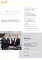
Terms of Sale, Delivery and Payment OUR COMPANY HISTORY 1890 Company founded as a lock manufacturer by Andreas Maier. 1920 Product range extended to include spanners. 1928 Production line assembly of FELLBACH LOCKS. WE GENERATE EXCITEMENT. Since the foundation of the company in 1890 until today the 1951 Introduces clamping elements and diversifies into workpiece and tool clamping technology. 1965 Toggle clamps extend the AMF product range, AMF catalogues are now printed in ten languages. goal has remained the same: the highest quality in products 1975 Further specialisation into hydraulic...
Open the catalog to page 2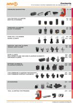
For an overview in numerical / alphabetical order, see catalouge pages 374 - 380 pressure generators hollow rod cylinders built-in cylinders threaded cylinders block cylinders push-pull cylinders swing clamps vertical and link clamps toggle joint clamp bore clamps pull down clamp and side clamping elements centring clamps support elements clamping elements low-pressure clamping technology low-pressure support elements tool clamping for Presses ANDREAS MAIER GmbH & Co. KG ∙ Phone: +49 711 5766-196 ∙ Web: www.amf.de Hydraulic clamping systems
Open the catalog to page 3
! NEW Vertical clamp with pivot arm 6958DH, page 140-141 ! NEW Clamping arm Vertical clamp, flange design Link clamp, double-sided 6959ED, page 168-169 Compensating collet 6965-20, page 236 Clamping lever, Standard and blank 6965-20-XX, page 237 6965-20-09, page 237 Hydraulic clamping systems ANDREAS MAIER GmbH & Co. KG ∙ Phone: +49 711 5766-196 ∙ Web: www.amf.d
Open the catalog to page 4
CONVENIENT ORDERING – IN OUR ONLINE SHOP + Over 6000 products can be ordered online + Order tracking online + Easy download of CAD data + Online inquiry of availability + Management of different shopping carts
Open the catalog to page 5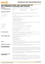
Important and interesting facts Recommendations and parameters of oil-hydraulic devices and plants. gener al: All parameters are published in accordance with the DIN regulations. designation to DIN 51 524 HL, HLP 22 or HLPD 22 HL, HLP 32 or HLPD 32 Cl amping elements: Pressure range: At continuous pressures below 80 bar, this must be stated on ordering as a dif ferent seal combination may need to be selected. Ambient temperature: Thermal expansion: If thermal expansion is prevented in a hydraulic system, the pressure rises by about 10 bar per 1 °C temperature increase. Such conditions...
Open the catalog to page 6
Important and interesting facts Hydraulic parameters, units and formula symbols: Ef fective piston area A Return spring The units used in this catalogue for physical quantities are in accordance with Technical equations: Clamping force: F (N) = 10 x A (cm ) x p (bar) Effective piston area Required operating pressure: Clamping time: Cl amping force of bolts: For hydraulic clamping, the fatigue strength of the bolts Clamping bolts Thread is considered to obtain a high number of strokes. The testing force or yield strength must only be utilized for cylinder selection: These sizes correspond to...
Open the catalog to page 7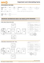
Important and interesting facts Conversion factors: Pressure: MPa 1 MPa MPa = Megapascal PSI = lb/sq. inch K = Kelvin °C = degree Celsius °F = degree Fahrenheit Important information about our installation drawings. All installation drawings in this catalogue are in first-angle projection (DIN)! Location of other views in relation to front elevation, V: D Plan view Side elevation from left Side elevation from right Bottom view Rear view Third-angle projection (ANSI / USA) Location of other views in relation to front elevation, V: D Plan view Side elevation from left Side elevation from...
Open the catalog to page 8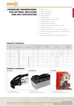
Pressure generators: the optimal solution for any applicaton > easy to use > ready for connection > ready for operation > variety of options > compact design > single and double-acting variants > modular design of pump > various valve combinations > available with and without electric controller > external control optional > continuous pressure control by adjustment spindle > valves in the de-energised condition in locked position > ecological operation > electric motors conform to efficiency classes of 2017 Product overview: Type single acting double acting Clamping circuits Output flow >...
Open the catalog to page 9
Screw Pump block version and built-in version, max. operating pressure 350 bar. stroke volume total [cm³] Housing from steel, hardened and burnished. Threaded spindle hardened and burnished. Screw pump no. 6901-20 is supplied with 2 grooved nuts. Oil supply via threaded port. The screw pump is particularily suitable to operate small clamping fixtures. For an enclosed circuit the following has to be considered: The hydraulic clamping elements connected to the screw pump have to be hermetically tight. Due to possible leakage of the clamping cylinders during stroke movement and the...
Open the catalog to page 10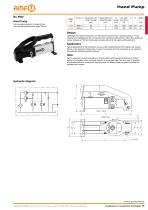
Hand Pump max. operating pressure 1st stage 50 bar, max. operating pressure 2nd stage 700 bar. Displacement per stroke 1st stage [cm³] Displacement per stroke 2nd stage [cm³] max. hand lever force [N] Lightweight two-speed hand-pump. Low hand force required at max. operating pressure. Pump housing from malleable cast iron, oil reservoir from aluminium. With pressure relief valve, factory set at max. pressure of 700 bar. Hand pump complete with oil fill. Oil supply via threaded port. Typical applications for the hand-pump are e.g. small clamping fixtures with irregular use, testing fixtures...
Open the catalog to page 11All ANDREAS MAIER GmbH & Co. KG (AMF) catalogs and technical brochures
-
HAND TOOLS
76 Pages
-
STANDARD CLAMPING ELEMENTS
172 Pages
-
TOGGLE CLAMPS
188 Pages
-
LOCKS FOR GATES AND DOORS
104 Pages
-
ZERO-POINT-SYSTEMS
228 Pages
-
SMART AUTOMATION
9 Pages
-
Free-form clamping
3 Pages
-
VACUUM CLAMPING SYSTEMS
24 Pages
-
MAGNETIC CLAMPING SYSTEMS
20 Pages
-
GRIPPER
20 Pages
-
WIRELESS SENSORING SYSTEMS
28 Pages
-
MARKING AND CLEANING TOOLS
32 Pages
-
AMF-Imagebrochure
14 Pages
Archived catalogs
-
Spectacular prices 2024
16 Pages


