
Catalog excerpts

SBS®X-75A Assembly Instructions NOTE: For easiest construction it is recommended to not strip or crimp wires onto cable until after step 1. Should customer choose to crimp contacts and insert contacts on wires thru grommet during installation, grommet should be inspected for any damage that may have occurred during installation to both external and internal ribs. Silicone debris left on wire and external tears or cracks on the grommet are clear indicators of damage. Damaged grommets should be discarded and replaced as a water-tight seal cannot be ensured if damage to grommet has occurred. Step 1 Slide grommet over power wires and signal or ground cable (if present) (see figure 1). Slide down far enough for wires to be fully inserted into housing; approximately 3.0” [118 mm]. It is recommended to have the signal cable cut 0.200” to 0.300” [5.1 to 7.6 mm] longer than the power wire to eliminate strain on the signal positions should the wires go under tension. For panel mount assemblies place panel gasket over back of housing prior to assembly. Step 2 Strip power wires as well as signal or ground wire/cable (if present). Ensure wires are stripped enough for completed insertion into contact crimp barrels (table A and figures 2 & 3). Table A: Cable Stripping Dimensions (0.56” [14.2 mm] Strip Length) (1.10” [28.0 mm] Strip Length)
Open the catalog to page 1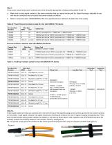
Step 3 Crimp power, signal and ground contacts onto wires using the appropriate crimping tooling (tables B and C). a. Make sure to crimp signal contacts in the same orientation that your signal housing will be. Signal Housing is intended for use with two pin contacts to be on top and two socket contacts on bottom. b. Refer to crimp document 1S6848 SBS®X-75A crimp specifications as reference to determine crimp quality. Table C: Auxiliary Contacts Listed for Use with SBS®X-75A Series Step 4a. Orient signal cable so the two pin contacts are in line with the top of the signal housing (arrow...
Open the catalog to page 2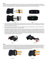
Step 5 Load both power contacts and signal/ground housing into the main connector body starting with the signal/ground housing and then the power contacts (see figure 5). Ensure both power contacts are fully seated on their respective springs and the signal/ground housing is completely latched into place. Signal Housing should be flush with front of the connector (see in figure 6). There are four keying positions that the signal or ground housing can be placed in as noted by hood position and direction of arrow on rear of housing (up, down, left, and right). Each position will key the...
Open the catalog to page 3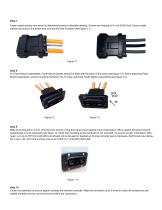
Step 7 Fasten cable clamps onto wires by alternating evenly to alleviate skewing. Screws are torqued to 6 in-lb [0.68 N-m]. Ensure cable clamps are snug to the power wire and ground wire if present (see figure 11). Step 8 For Panel Mount assemblies, Panel Mount Gasket should be flush with the back of the panel (see figure 12). When attaching Panel Mount assemblies, ensure mounting hardware has O-rings under bolt heads before assembling (see figure 13). Step 9 Bolts to be torqued to 3 in-lb. [0.34 N-m] to ensure O-ring and panel mount gasket have compression. Minor gasket extrusion beyond...
Open the catalog to page 4
IP68 Protection – Unmated Anderson strongly recommends the usage of covers when connectors are not mated to maintain IP68 protection. To tether connector covers to the housings, first pull through geometry on the housings. Then pull cover through loop on end of cord. Finally, pull tight to secure cord loop around connector (see figure series 15 & 16) for example process. For panel mount assemblies, simply replace a mounting O-ring with tethered grommet. (see figure series 17) for example process. Figure Series 15 - Receptacle Cover Figure Series 17 - Panel Mount Cover Figure Series 16 -...
Open the catalog to page 5
All Data Subject to Change Without No ce 1S6859 2023‐0092 Rev 2 Your Best Connec on™ Anderson™ will use reasonable efforts to include accurate and up‐to‐date content in the assembly instruc on. All product informa on contained in the instruc on sheet including ordering informa on, illustra ons, specifica ons, and dimensions, are believed to be reliable as of the date of publishing, but is subject to change without no ce. Anderson™ makes no warranty or representa on as to its accuracy. Content in the instruc on sheet may contain technical inaccuracies, typographical errors and may be changed...
Open the catalog to page 6All Anderson Power Products catalogs and technical brochures
-
GLOBAL SUPPLIER MANUAL
38 Pages
-
Powerpole® & Multipole
140 Pages
-
Saf-D-Grid®
12 Pages
-
Powerpole&Multipole Connectors
124 Pages
-
Appilcation Tooling Overview
1 Pages
-
Datacenter Application Guide
6 Pages
-
E-MOBILITY
6 Pages
-
Power Connector Solutions
2 Pages
-
Compact Power Connectors
102 Pages


