- Catalogs
- Anderson-Negele | Negele Messtechnik GmbH
- ITM-51, ITM-51R
ITM-51, ITM-51R
1 /8Pages

ITM-51, ITM-51R
1 /8Pages
Catalog excerpts

SENSORS FOR FOOD AND BIOPHARMA. ANDERSON-NEGELE Product Information ITM-51 | ITM-51R FOOD Relative Turbidity Meter ITM-51 /CLEANadapt! Application / Specified Usage ■ Relative turbidity measurement of liquid media for mid to high turbidity range (200...300,000 NTU equivalent) 46-03 Application Examples ■ Phase separation of products (for example whey - cream - milk) ■ CIP-return line (monitoring of pre-rinse water to product leftovers) ■ Yeast harvest in breweries ■ Quality control ■ Leackage control of filter and gaskets ITM-51 Hygienic Design / Process Connection ■ By using Negele weld-in sleeves / adapters of the CLEANadapt system or the build-in system EHG-.../ 1/2" a flow optimized, hygienic and easy sterilizable installation will be achieved. ■ CIP-/SIP-cleaning up to 140 °C / maximum 120 minutes ■ Product contacting materials compliant to FDA ■ Sensor made of stainless steel ■ Optics made of high resistant sapphire ■ Process connection G1/2" hygienic, Tri-Clamp or Varivent, adapters available for milk pipe (DIN 11851), DRD, APV et al. (see CLEANadapt product information) ■ 3-A compliant Tri-Clamp process connection Features / Advantages ■ Front flush sensor ■ Independent to reflexions at small diameters or electro-polished surfaces ■ No color dependency (wave length 860 nm) ■ Smallest pipe diameter: DN 25 ■ High reproducibility: < 1% of full scale ■ Switching output (switchpoint and hysteresis freely adjustable) ■ Analog output 4...20 mA freely adjustable ■ Two ranges externally switchable ITM-51R Options / Accessories ■ Electrical connection with M12 plug-in connector ■ Preassembled cable for M12 plug-in connector ■ Display module Simple User Interface (SUI) and Large User Interface (LUI) ■ Remote version with cable length up to 30 m Measurement Principle Sensor Measuring Principle of the Relative Turbidity Meter An infrared diode irradiates infrared light into the media. Particles in the media reflecting the irradiated light which is detected by the receiver diode (backscatter principle). The electronics calculates the relative turbidity of the media according to the received signal. The relative turbidity is based on the Negele calibration standard and is displayed in ”%TU".
Open the catalog to page 1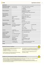
Specification | Advices Specification Mechanical Connection / Installation ■ The sensor has to be installed in that way that the sensor tip is entirely washed around by media and no bubbles can occure. Installation in a rising pipe is recommended. ■ If weld-in sleeve is correctly mounted the axis between the 2 connectors points in flow direction. ■ For installation in horizontal pipes from top the standard sensor with 15 mm sensor tip is recommended to avoid the influence of bubbles to the measuring signal. ■ Attention: The maximum tightening torque for mounting is 20 Nm! Conditions for a measuring...
Open the catalog to page 2
FOOD ITM-51 with vertical head orientation ITM-51 with horizontal head orientation Varivent size Tri-Clamp size
Open the catalog to page 3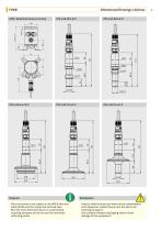
Dimensional Drawings | Advices HUR / Head Unit Remote Version ■ This instrument is not subject to the WEEE directive 2002/96/EG and the respective national laws. ■ Pass the instrument directly on to a specialised recycling company and do not use the municipal collecting points. ■ Sensors shall be clean and must not be contaminated with dangerous media! Please note the advice for cleaning on page 5! ■ Use suitable transport packaging only to avoid damage of the equipment!
Open the catalog to page 4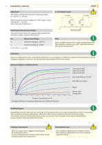
·· The factory setting of the device is measuring range 1 (0...100 % = 4...20 mA). ·· With an external control voltage (24 V DC) range 2 can be selected (E1 = 24 V DC). (See “Electrical Connection”) Switching the Measurement Range flow direction ·· The digital control input E1 is galvanically isolated from the power supply. Ground: clamp 9 (0 V) E1* Measurement Range Select suitable measurement range in applications with high turbidity variances (e.g. milk / milk water mixture) for precise measurement! Device is calibrated ex works. A periodical calibration is not neccessary. A calibration check...
Open the catalog to page 5
Electrical Connection | Installation FOOD Electrical Connection ITM-51 | ITM-51R Parameterization The turbidity meter ITM-51 / ITM-51R is set to operate without requiring special settings. Should the parameters need to be changed, this can be performed using the PC-based MPI-200 programming adapter or the User Interface. For further details please refer to the operating manual. Programming adapter MPI-200-F connection Connection plug for MPI-200-F adapter as an intermediate plug between the ITM-51 electronics and the MPI-200 connection 3 (see next figure). Power supply +24 V DC Power supply Digital...
Open the catalog to page 6
Order Code Order code ITM-51R (relative turbidity meter, remote version, remote cable must be ordered seperately) Process connection S0L (CLEANadapt G1/2", 15 mm sensor tip) MMX (further process connections on request) Output A42 (1 x 4...20 mA turbidity only, display prepared) A52 (1 x 4...20 mA turbidity, 1 x switching out, no external range switching, display prepared) A53 (1 x 4...20 mA turbidity, 1 x switching out, external range switching, display prepared) Electrical connection P (cable gland M16x1.5) M (1 x M12 connector, 4 pin for output A42, 5 pin for output A5x) N (2 x M12 plug, standard)...
Open the catalog to page 7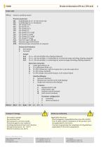
Product Information ITM-51 | ITM-51R Order code ITM-51 (relative turbidity meter) Process connection S0L (CLEANadapt G1/2", 15 mm sensor tip) MMX (further process connections on request) Enclosure Orientation H (horizontal) Output A42 (1 x 4...20 mA turbidity only, display prepared) A52 (1 x 4...20 mA turbidity, 1 x switching out, no external range switching, display prepared) A53 (1 x 4...20 mA turbidity, 1 x switching out, external range switching, display prepared) Electrical connection P (cable gland M16x1.5) M (1 x M12 connector, 4-pin for output A42, 5-pin for output A5x) A (2 x M12 plug,...
Open the catalog to page 8All Anderson-Negele | Negele Messtechnik GmbH catalogs and technical brochures
 Pt100-Simulator
1 Page
 Temperature Controller VTR-2
4 Pages
 LAR-361, LAR-761
8 Pages
 SX
SX4 Pages
 DPM
DPM8 Pages
 NSL-F-02
4 Pages
 HMP-E Flow Sensors
8 Pages
 ILM-4 Conductivity Sensors
8 Pages
 ITM-3 Turbidity Sensors
8 Pages
 ITM-4 Turbidity Sensors
8 Pages
 ITM-4DW Turbidity Sensors
8 Pages
 Anderson-Negele Product Overview
28 Pages
 Conductive Multilevel Sensor
8 Pages
 NVS-141...186
8 Pages
 NSS-157_50032_5.0
4 Pages
 VNV-ZNV_50064_4.0
8 Pages
 NSL-F-00-01_50060_1.4
12 Pages
 L3_50093_1.0
8 Pages
 Product info NSL-M
8 Pages


- Fitting
- Flowmeter
- Hydraulic fitting
- Screw-in fitting
- Temperature probe
- Volume flow monitor
- Liquid flow monitor
- Stainless fitting
- Resistance temperature sensor
- Pressure transmitter
- Pressure gauge
- Level limit switch
- Analog pressure transmitter
- Liquid level detector
- Level probe
- Stainless steel flow monitor
- Liquid level sensor
- Digital pyrometer
- Plastic fitting
- Digital indicator