- Catalogs
- Anderson-Negele | Negele Messtechnik GmbH
- ITM-4DW Turbidity Sensors
ITM-4DW Turbidity Sensors
1 /8Pages

ITM-4DW Turbidity Sensors
1 /8Pages
Catalog excerpts
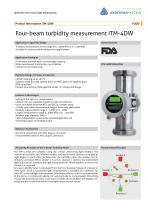
SENSORS FOR FOOD AND BIOPHARMA. Four-beam turbidity measurement ITM-4DW Application / Specified Usage ·· Turbidity measurement in the range of 0...5000 NTU or 0...1250 EBC ·· Suitable for process and drinking water applications Application Examples ·· Fresh water monitoring in the beverage industry ·· Water/wastewater monitoring, e.g. in dairies ·· Coolant circuit monitoring Hygienic Design / Process Connection ·· CIP/SIP cleaning up to 130 °C ·· Stainless steel housing, optical block of PPSU, optics of sapphire glass (FDA compliant) ·· Process connections: Milk pipe DIN 11851, Tri-Clamp, DIN flange Features / Advantages ·· Soiling of the optics is compensated ·· Compact device; separate evaluation unit not required ·· Units switchable between NTU and EBC (11 ranges each) ·· 4 freely selectable measurement ranges, externally switchable ·· Smallest measurement range 0...5 NTU or 0...1 EBC ·· Largest measurement range 0...5000 NTU or 0...1250 EBC ·· Smallest pipe diameter DN25 ·· Color-independent measurement (wavelength 860 nm) ·· Switching output and analog output Options / Accessories ·· Electrical connection with M12 plug-in connector ·· Preassembled cable for M12 plug-in connector Measuring Principle of the 4-Beam-Turbidity Meter The ITM-4 measures turbidity using the 4-beam alternating light method. The transmitter contains two infrared senders and two infrared receivers arranged at right angles to each other. To determine the turbidity value, the senders are alternately activated. When sender 1 is active, receiver 1 detects the transmitted light and receiver 2 detects the light scattered at 90°. When sender 2 is active, the situation is reversed. An exact turbidity value is calculated from the four measured values of a measurement cycle. Since a transmitted light measurement is available as a reference for each 90° scattered light measurement, interference factors such as contamination of the optics or component ageing can automatically be compensated. Disturbing infl uences from the sporadic occurrence of solids and air bubbles are largely cancelled out due to the evaluation of multiple measurement cycles. Measurement Principle Sender 2
Open the catalog to page 1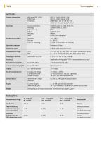
Technical data Specification
Open the catalog to page 2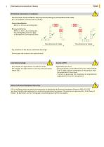
Mechanical connection | Notes Mechanical Connection / Installation ·· The device has to be installed in that way that the fitting is entirely filled with media. Air or air bubbles are detected as turbidity. ·· Correct installation: ·· Before or into an ascending pipe. ·· Wrong installation: ·· Before or into a descending pipe. ·· Into the highest point of a pipe, air bubbles will concentrate there Flow direction of media Flow direction of media ·· Pay attention to the above-mentioned drawings! ·· Do not open the screws at the optical block! Conventional Usage ·· Not suitable for applications...
Open the catalog to page 3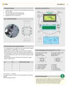
Installation Electrical connection ITM-4 Turning the display 1. Loosen the set screws (1) on top and bottom resp.on the left and right. 2. Turn the head to the desired position. Turnig is possible only in steps of 90°! 3. Tighten the two set screws (1). Fig.: Turning the display External measurement range selection • The turbidity meter is delivered with measurement range 1 (0...1000 NTU / 0-1000 EBC = 4...20 mA) • Range 2 (E1=24 V DC), range 3 (E2=24 V DC) and range 4 (E1=24 V DC and E2=24 V DC) can be chosen by means of the ratedsignal +24 V DC (18...36 V DC) at the inputs on pin 7, 8 and 9....
Open the catalog to page 4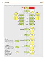
Display Ttirbldlty Measuring Unit After Imin, the device automatically switches back to display mode. Legend A-Symbol "current output overload": will be displayed if the measured value is higher than the measurement range. Iout: > 20 mA (max. 21.6 mA) AAAA-Symbol the current measured value is higher than 5000 NTU resp. 1250 EBC Iout: > 20 mA (max. 21.6 mA) 1 (top left) current editable measurement ◊-Symbol (bottom left) the value aside is now editable by using the arrow-buttons Switching Point Switch Function
Open the catalog to page 5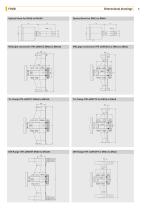
Dimensional drawings Optical block for DN50 to DN100 Milk pipe connection ITM-4DW/GG DN50 to DN100 Milk pipe connection ITM-4DW/GG for DN25 to DN40
Open the catalog to page 6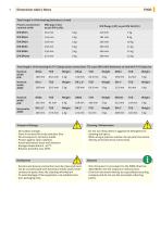
Dimensions table | NotesTransport/Storage Cleaning / Maintenance Total length L of the housing (tolerance ±2 mm) ■ Do not use sharp items or aggressive detergents for cleaning the optics. ■ When using a pressure washer, do not point the nozzle directly at the electrical connections. ■ No outdoor storage ■ Store in an area that is dry and dust-free ■ Do not expose to corrosive media ■ Protect against solar radiation ■ Avoid mechanical shock and vibration ■ Storage temperature 0...40 °C ■ Relative humidity max. 80% ■ Sensors and process connection must be clean and must not be contaminated with...
Open the catalog to page 7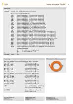
Product Information ITM-4DW Order Code ITM-4DW (Material PPSU with drinking water certification) Process connection for DN40 Optics TC25 (Nominal width DN25; Tri-Clamp process connection) TC40 (Nominal width DN40; Tri-Clamp process connection) TC50 (Nominal width DN50; Tri-Clamp process connection) TC65 (Nominal width DN65; Tri-Clamp process connection) TC80 (Nominal width DN80; Tri-Clamp process connection) TC100 (Nominal width DN100; Tri-Clamp process connection) TC1 (Nominal width ASME 1"; Tri-Clamp process connection) TC1.5 (Nominal width ASME 1%"; Tri-Clamp process connection) TC2 (Nominal...
Open the catalog to page 8All Anderson-Negele | Negele Messtechnik GmbH catalogs and technical brochures
 Pt100-Simulator
1 Page
 Temperature Controller VTR-2
4 Pages
 ITM-51, ITM-51R
8 Pages
 LAR-361, LAR-761
8 Pages
 SX
SX4 Pages
 DPM
DPM8 Pages
 NSL-F-02
4 Pages
 HMP-E Flow Sensors
8 Pages
 ILM-4 Conductivity Sensors
8 Pages
 ITM-3 Turbidity Sensors
8 Pages
 ITM-4 Turbidity Sensors
8 Pages
 Anderson-Negele Product Overview
28 Pages
 Conductive Multilevel Sensor
8 Pages
 NVS-141...186
8 Pages
 NSS-157_50032_5.0
4 Pages
 VNV-ZNV_50064_4.0
8 Pages
 NSL-F-00-01_50060_1.4
12 Pages
 L3_50093_1.0
8 Pages
 Product info NSL-M
8 Pages


- Flowmeter
- Hydraulic fitting
- Screw-in fitting
- Temperature probe
- Volume flow monitor
- Liquid flow monitor
- Stainless fitting
- Resistance temperature sensor
- Pressure transmitter
- Level limit switch
- Pressure gauge
- Analog pressure transmitter
- Liquid level detector
- Level probe
- Liquid level sensor
- Stainless steel flow monitor
- Digital pyrometer
- Digital indicator
- Plastic fitting