
- Catalogs
- Analog Devices
- Single-Supply Sensor Interface Amplifier


- Products
- Catalogs
- News & Trends
- Exhibitions
Single-Supply Sensor Interface Amplifier

Single-Supply Sensor Interface Amplifier
Catalog excerpts
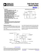
Single-Supply Sensor Interface Amplifier AD22057 FEATURES Gain of ⴛ20. Alterable from ⴛ1 to ⴛ160 Input CMR from Below Ground to 6ⴛ (VS – 1 V) Output Span 20 mV to (VS – 0.2) V 1-, 2-, 3-Pole Low-Pass Filtering Available Accurate Midscale Offset Capability Differential Input Resistance 400 k⍀ Drives 1 k⍀ Load to +4 V Using VS = +5 V Supply Voltage: +3.0 V to +36 V Transient Spike Protection and RFI Filters Included Peak Input Voltage (40 ms): 60 V Reversed Supply Protection: –34 V Operating Temperature Range: –40ⴗC to +125ⴗC FUNCTIONAL BLOCK DIAGRAM +VS APPLICATIONS Current Sensing Motor Control Interface for Pressure Transducers, Position Indicators, Strain Gages, and Other Low Level Signal Sources Accelerometers GENERAL DESCRIPTION The AD22057 is a single-supply difference amplifier for amplifying and low-pass filtering small differential voltages (typically 100 mV FS at a gain of 40) from sources having a large commonmode voltage. Supply voltages from +3.0 V to +36 V can be used. The input common-mode range extends from below ground to +24 V using a +5 V supply with excellent rejection of this common-mode voltage. This is achieved by the use of a special resistive attenuator at the input, laser trimmed to a very high differential balance. Provisions are included for optional low-pass filtering and gain adjustment. An accurate midscale offset feature allows bipolar signals to be amplified. SOLENOID LOAD POWER DARLINGTON SINGLE-POLE LOW-PASS FILTERING, GAIN: 40 ANALOG GROUND Figure 1. Typical Application Circuit for a Current Sensor Interface Document Feedback Information furnished by Analog Devices is believed to be accurate and reliable. However, no responsibility is assumed by Analog Devices for its use, nor for any infringements of patents or other rights of third parties which may result from its use. No license is granted by implication or otherwise under any patent or patent rights of Analog Devices. One Technology Way, P.O. Box 9106, Norwood, MA 02062-9106, U.S.A. Tel: 781.329.4700 ©2017 Analog Devices, Inc. All rights reserved. www.anal
Open the catalog to page 1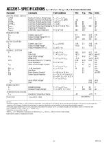
= 0, RL = 10 k⍀ unless otherwise noted) Test Conditions INPUTS (PINS 1 AND 8) +CMR CMR CMRRLF CMRRHF RINCM RMATCH RINDIFF Positive Common-Mode Range Negative Common-Mode Range Common-Mode Rejection Ratio Common-Mode Rejection Ratio Common-Mode Input Resistance Matching of Resistances Differential Input Resistance TA = TMIN to TMAX TA = TMIN to +85°C f ≤ 10 Hz f = 1 kHz Pin 1 or Pin 8 to Pin 2 Closed-Loop Gain1 Output Voltage Range (Pin 3) Output Resistance2 Closed-Loop Gain1 Output Voltage Range3 Output Resistance (Pin 5) Gain1 Gain Drift Input Offset Voltage4 Offset Drift Midscale Offset (Pin...
Open the catalog to page 2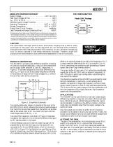
AD22057 ABSOLUTE MAXIMUM RATINGS* Supply Voltage . . . . . . . . . . . . . . . . . . . . . . . . +3.0 V to +36 V Peak Input Voltage (40 ms) . . . . . . . . . . . . . . . . . . . . . . +60 V VOFS (Pin 7 to Pin 2) . . . . . . . . . . . . . . . . . . . . . . . . . . . . +20 V Reversed Supply Voltage Protection . . . . . . . . . . . . . . . –34 V Operating Temperature . . . . . . . . . . . . . . . . –40°C to +125°C Storage Temperature . . . . . . . . . . . . . . . . . . –65°C to +150°C Output Short Circuit Duration . . . . . . . . . . . . . . . . Indefinite Lead Temperature Range (Soldering 60 sec)...
Open the catalog to page 3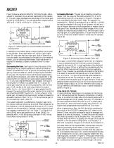
AD22057 Figure 3 shows a general method for trimming the gain, either upward or downward, by an amount dependent on the resistor, R. The gain range, expressed as a percentage of the overall gain, is given by (10 MΩ/R)%. Thus, the adjustment range would be ± 2% for R = 5 MΩ; ± 10% for R = 1 MΩ, etc. ANALOG OUTPUT +IN VDM Increasing the Gain. The gain can be raised by connecting a resistor from the output of the buffer amplifier (Pin 5) to its noninverting input (Pin 4) as shown in Figure 5. The gain is now multiplied by the factor R/(R–100k); for example, it is doubled for R = 200 kΩ. Overall...
Open the catalog to page 4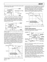
AD22057 frequency will increase; it should be calculated using the parallel sum of the resistor and 100 kΩ. ANALOG OUTPUT A three-pole filter (with roll-off 60 dB/decade) can be formed by adding a passive RC network at the output forming a real pole. A three-pole filter with a corner frequency f3 has the same attenuation a one-pole filter of corner f1 has at a frequency √f33/f1, where the attenuation is 30 Log (f3/f1) (see the graph in Figure 9). Using equal capacitor values, and a resistor of 160 kΩ, the corner-frequency calibration remains 1 Hz-µF. FREQUENCY ATTENUATION ANALOG COMMON Figure...
Open the catalog to page 5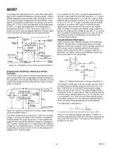
AD22057 To produce a full-scale output of +4 V, a gain ×40 is used, adjustable by ±5% to absorb the tolerance in the sense resistor. There is sufficient headroom to allow at least a 10% overrange (to +4.4 V). The roughly triangular voltage across the sense resistor is averaged by a single-pole low-pass filter, here set with a corner frequency of fC = 3.6 Hz, which provides about 30 dB of attenuation at 100 Hz. A higher rate of attenuation can be obtained by a two-pole filter having fC = 20 Hz, as shown in Figure 11. Although this circuit uses two separate capacitors, the total capacitance is...
Open the catalog to page 6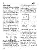
AD22057 APPLICATION HINTS Frequency Compensation As are all closed-loop op amp circuits, the AD22057 is sensitive to capacitive loading at its output. However, the AD22057 is sensitive at higher output voltages due to nonlinear effects in the rail-to-rail design of the buffer amplifier (A2). In this amplifier the output stage gain increases with increasing output voltage. This behavior does not affect dc parameters such as gain accuracy or linearity; however, it can compromise ac stability. When operating from a power supply of 5 V or less (and, therefore, VOUT < 5 V), the AD22057 can drive capacitive...
Open the catalog to page 7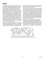
AD22057 Key filter can be formed (see Low-Pass Filtering section) and also provides a means for setting the overall gain to values other than ×20 (see Altering the Gain section). A unique method of feedback around A1, provided by R9 and R7, sets the closed-loop gain of the preamplifier to ×10 (from the input pins). The feedback network is balanced by the inclusion of R6 and R8. The small value of R7 results in a more practical value for R9 (which would have to be 2 MΩ if the feedback were taken directly to the inputs of A1). R8 is not directly connected to ground, but to an optional voltage of...
Open the catalog to page 8All Analog Devices catalogs and technical brochures
 HMC722LP3E
8 Pages
 Isolated Sigma-Delta Modulator
17 Pages
 HMC853 Data Sheet
10 Pages
 AN-1084
8 Pages
 AN-1091
2 Pages
 AN_737
8 Pages
 AN-0982
4 Pages
 ADF7024
24 Pages
 AD9915
48 Pages
 AD9914
48 Pages
 ADRF6612
59 Pages
 ADRF6820
48 Pages
 ADL5246
32 Pages
 ADA4961
22 Pages
 AN-1141
8 Pages
 AN-698
36 Pages
 Temperature Sensors
2 Pages
 Reference Circuits
8 Pages
 Precision ADCs
16 Pages
 ADR02ACHIPS: ADR02ACHIPS
8 Pages
 AD9364 RF Agile Transceiver
32 Pages
 Digital Temperature Sensors
2 Pages
 Digital to Analog Converter ICs
12 Pages
 AD1836A: Multichannel 96 kHz Codec
24 Pages












































Archived catalogs
 Zero-Drift Amplifiers
2 Pages
 Powering ADI Components
8 Pages








- Ethernet switch
- Industrial network switch
- Unmanaged switch
- Analog Devices motor controller
- Transceiver module
- Triaxial acceleration sensor
- DC motor controller
- Data acquisition unit
- Analog Devices stepper motor controller
- Industrial converter
- Ethernet transceiver
- Processor
- High-voltage amplifier
- Low-noise amplifier
- Multiplexer
- Compact motor controller
- Digital converter
- Closed-loop motor controller
- Digital motor controller