- Catalogs
- Analog Devices
- AN-1084
AN-1084
1 /8Pages

AN-1084
1 /8Pages
Catalog excerpts
AN-1084 APPLICATION NOTE One Technology Way • P.O. Box 9106 • Norwood, MA 02062-9106, U.S.A. • Tel: 781.329.4700 • Fax: 781.461.3113 • www.analog.com Channel Switching: AD7190, AD7192, AD7193, AD7194, AD7195 by Mary McCarthy INTRODUCTION Σ-Δ ADCs are generally specified in terms of output data rate. The output data rate is the rate at which conversions are performed when a single channel is selected and the ADC is continuously converting. In a multichannel application such as a data acquisition system, conversions from several channels are read; that is, each channel is selected in turn and a conversion is performed for that channel. In such an application, the rate at which conversions are performed can be different from a single channel system. This application note describes the switching procedure used by the AD7190, AD7192, AD7193, AD7194, and AD7195 parts (hereafter referred to as AD719x). MULTICHANNEL SYSTEM In applications such as PLC systems, several input channels are required to process the multitude of signals or outputs from sensors. With its PGA and wide range of programmable output data rates, the AD719x can be used to convert signals of different amplitudes and at different output data rates. The application generally requires a certain throughput, that is, a given number of channels need to be read within a given period of time. The throughput achieved is dependent on the number of channels to be read and the time taken by the ADC to convert each channel. The ADCs referred to in this application note have several modes of operation: • • • • • Sinc4 filter or Sinc3 filter Chop enabled/disabled Zero latency Single conversion mode Automatic channel sequencing The output data rates allowed and/or the settling time (the time taken to generate the first conversion after a channel change) is different for each mode of operation. Therefore, the throughput also depends on the operating mode.
Open the catalog to page 1
Application Note REVISION HISTORY 9/10—Revision 0: Initial Version
Open the catalog to page 2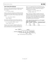
Application Note SINC4 FILTER (CHOP DISABLED) When the sinc4 filter is selected and chop is disabled, the output data rate when continuously converting on a single channel (fADC) is equal to rate (fADC). In an application where several channels are used and one conversion is read from each channel, the settling time is required for every conversion. Therefore, the number of channels read per second equals Throughput = fCLK/(4 × 1024 × FS[9:0] + 507) where fCLK is the master clock frequency and FS[9:0] is the filter word loaded into the mode register. The time required to generate the first conversion...
Open the catalog to page 3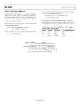
Application Note SINC3 FILTER (CHOP DISABLED) 3 The digital filter can be changed to a sinc filter by setting the SINC3 bit in the mode register. Choosing the sinc3 filter does not affect the output data rate. Therefore, the output data rate when continuously converting on a single channel is again fADC = fCLK/(1024 × FS[9:0]) However, the time required to generate a valid conversion after a channel change is reduced. Throughput = fCLK/(3 × 1024 × FS[9:0] + 507) = fCLK/(3072 × FS[9:0] + 507) Table 2 gives a summary of the output data rate, settling time, and throughput for some sample FS[9:0]...
Open the catalog to page 4
Application Note CHOPPING ENABLED When the sinc3 filter is selected and chop is enabled, the output data rate when continuously converting on a single channel is With the sinc4 filter selected and chop enabled, the output data rate when continuously converting on a single channel, fADC, is The settling time is tSETTLE = 2/(fCLK/(1024 × FS[9:0] × 3 + 16)) + 491/fCLK The time required to generate a conversion following a channel change (settling time) equals tSETTLE = 2/(fCLK/(1024 × FS[9:0] × 4 + 16)) + 491/fCLK = (6144 × FS[9:0] + 523)/fCLK For low output data rates, these equations can be approximated...
Open the catalog to page 5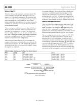
Application Note For example, if the sinc4 filter is selected, chop is disabled and zero latency is enabled, the output data rate equals 12.5 Hz when FS = 96. Therefore, the conversion time is 80 ms. The settling time is 80.1 ms. Up to 12 channels can be sampled per second when FS = 96. Therefore, the throughput is the same as for the sinc4, chop disabled, zero latency disabled configuration. ZERO LATENCY These Σ-Δ ADCs can also operate in zero latency mode. This mode is enabled by setting Bit MR11 (Bit Single) in the mode register to 1. When this mode is enabled, the conversion time when continuously...
Open the catalog to page 6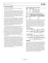
Application Note CHANNEL SEQUENCER Table 6. Settling Time (Sequencer Enabled) The value of the FS[9:0] bits and the operating mode used are the main factors that affect the throughput rate. However, in all the modes described thus far, the user must write to the configuration register between conversions to select the next channel for conversion. In single conversion mode, the user must write to the mode register in addition to the configuration register to initiate another single conversion. These ADCs have an on-chip channel sequencer that simplifies the use of the parts in multichannel applications....
Open the catalog to page 7
Application Note ©2010 Analog Devices, Inc. All rights reserved. Trademarks and registered trademarks are the property of their respective owners. AN09246-0-9/10(0)
Open the catalog to page 8All Analog Devices catalogs and technical brochures
 HMC722LP3E
8 Pages
 Isolated Sigma-Delta Modulator
17 Pages
 HMC853 Data Sheet
10 Pages
 AN-1091
2 Pages
 AN_737
8 Pages
 AN-0982
4 Pages
 ADF7024
24 Pages
 AD9915
48 Pages
 AD9914
48 Pages
 ADRF6612
59 Pages
 ADRF6820
48 Pages
 ADL5246
32 Pages
 ADA4961
22 Pages
 AN-1141
8 Pages
 AN-698
36 Pages
 Temperature Sensors
2 Pages
 Reference Circuits
8 Pages
 Precision ADCs
16 Pages
 ADR02ACHIPS: ADR02ACHIPS
8 Pages
 AD9364 RF Agile Transceiver
32 Pages
 Digital Temperature Sensors
2 Pages
 Digital to Analog Converter ICs
12 Pages
 AD1836A: Multichannel 96 kHz Codec
24 Pages


Archived catalogs
 Zero-Drift Amplifiers
2 Pages
 Powering ADI Components
8 Pages


- Ethernet switch
- Industrial network switch
- Acceleration sensor
- Unmanaged switch
- Transceiver module
- Analog Devices motor controller
- Triaxial acceleration sensor
- DC motor controller
- Analog Devices stepper motor controller
- Industrial converter
- Ethernet transceiver
- Processor
- High-voltage amplifier
- Low-noise amplifier
- Multiplexer
- Compact motor controller
- Gyroscope
- Closed-loop motor controller
- Digital converter