- Catalogs
- Analog Devices
- AN-0982
AN-0982
1 /4Pages

AN-0982
1 /4Pages
Catalog excerpts
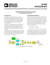
AN-0982 APPLICATION NOTE One Technology Way • P.O. Box 9106 • Norwood, MA 02062-9106, U.S.A. • Tel: 781.329.4700 • Fax: 781.461.3113 • www.analog.com The Residual Phase Noise Measurement by David Brandon and John Cavey BACKGROUND INFORMATION This application note describes a technique to evaluate DUT noise by removing external noise sources. A residual phase noise setup is used to isolate and measure the additive phase noise contribution of a device. Designers use this information to select individual devices for their signal chain, which, in aggregate, meet the phase noise requirements for their complete system. The setup shown in Figure 1 measures the additive phase noise of the DUT. Note that two DUTs are used, each connected to a common power supply and a common input clock. It will be shown that the noise at each DUT output due to these common noise sources is correlated. If the amplified DUT1 output signal is denoted as E1 and the amplified and delayed DUT2 output signal is denoted as E2, then the output phase noise can be derived by simply modeling the phase detector as an analog multiplier with a gain of KPD. The benefit of a residual phase noise setup is that the effect of noise sources external to the device under test (DUT), such as power supplies or input clocks, can be canceled from the measurement. Conversely, an absolute phase noise measurement includes the impact of power supply noise and reference clock noise. This application note includes actual phase noise measurement plots of a clocked device to highlight the attributes of the residual phase noise setup. In addition, it demonstrates how the additive phase noise of a device can be used to identify the source of noise-related issues in the signal chain. E1 = EC1 cos[ωCt + θM1 cos(ωMt)] E2 = EC2 sin[ωCt + θM2 cos(ωMt)] EOUT = LPF {KPDE1E2} = KPDEC1EC2 sin [(θM2 – θM1)cos(ωMt)] The signal powers are assigned ECX and the magnitude of the phase modulation (noise) is assigned θMX with carrier frequency ωC and modulating (offset) frequency ωM. Because superposition applies, the phase noise intrinsic to the DUTs can be neglected when considering the phase noise from external sources. POWER SPLITTER PHASE DETECTOR SPECTRUM ANALYZER Figure 1. Residual Phase Noise Measurement Setup CLOCK SOURCE MAGNITUDE (dBc/Hz)
Open the catalog to page 1
Application Note Considering the input clock signal phase noise and assuming that DUT1 and DUT2 have identical excess phase transfer functions, it is apparent by inspection that the portion of θM1 due to the clock source is equivalent to the portion of θM2 due to the clock source. Similarly, the portion of θM1 due to the power supplies is equivalent to the portion of θM2 due to the power supplies. This phenomenon can be considered supply pushing and is simply described by gain and noise figure of the amplifiers resemble one another as closely as possible. Note that a DUT that requires clocking...
Open the catalog to page 2
Application Note CLOCK SOURCE 1 WITH COMMON POWER SUPPLY CLOCK SOURCE 2 WITH COMMON POWER SUPPLY CLOCK SOURCE 1 WITH SEPARATE POWER SUPPLIES MAGNITUDE (dBc/Hz) MAGNITUDE (dBc/Hz) Figure 2. Absolute Phase Noise Measurement of Two Different Clock Sources –90 CLOCK SOURCE 1 WITH COMMON POWER SUPPLY CLOCK SOURCE 2 WITH COMMON POWER SUPPLY MAGNITUDE (dBc/Hz) Figure 4. Residual Phase Noise Measurement Displays the Impact from Common and Separate Power Supplies The same model (noisy) power supply is used for producing Figure 3 and Figure 4. The measured phase noise impact of this power supply becomes...
Open the catalog to page 3
Application Note The residual phase noise measurement is a valuable technique used to identify the phase noise contribution of a single component as part of a system design. Using this approach external noise sources, such as the input clock signal noise and power supply noise, can be effectively cancelled since these noise contributors are correlated at each DUT in the measurement setup. Furthermore, it is possible to account for the phase noise contribution of buffers or amplifiers used in the DUT residual noise measurement by performing additional residual phase noise measurements on these...
Open the catalog to page 4All Analog Devices catalogs and technical brochures
 HMC722LP3E
8 Pages
 Isolated Sigma-Delta Modulator
17 Pages
 HMC853 Data Sheet
10 Pages
 AN-1084
8 Pages
 AN-1091
2 Pages
 AN_737
8 Pages
 ADF7024
24 Pages
 AD9915
48 Pages
 AD9914
48 Pages
 ADRF6612
59 Pages
 ADRF6820
48 Pages
 ADL5246
32 Pages
 ADA4961
22 Pages
 AN-1141
8 Pages
 AN-698
36 Pages
 Temperature Sensors
2 Pages
 Reference Circuits
8 Pages
 Precision ADCs
16 Pages
 ADR02ACHIPS: ADR02ACHIPS
8 Pages
 AD9364 RF Agile Transceiver
32 Pages
 Digital Temperature Sensors
2 Pages
 Digital to Analog Converter ICs
12 Pages
 AD1836A: Multichannel 96 kHz Codec
24 Pages


Archived catalogs
 Zero-Drift Amplifiers
2 Pages
 Powering ADI Components
8 Pages


- Ethernet switch
- Industrial network switch
- Acceleration sensor
- Unmanaged switch
- Transceiver module
- Analog Devices motor controller
- Triaxial acceleration sensor
- DC motor controller
- Data acquisition unit
- Analog Devices stepper motor controller
- Industrial converter
- Ethernet transceiver
- Processor
- High-voltage amplifier
- Low-noise amplifier
- Multiplexer
- Compact motor controller
- Gyroscope
- Closed-loop motor controller
- Digital converter