- Catalogs
- Analog Devices
- ADUM2210: Dual-Channel Digital Isolators, 5 kV
ADUM2210: Dual-Channel Digital Isolators, 5 kV
1 /20Pages

ADUM2210: Dual-Channel Digital Isolators, 5 kV
1 /20Pages
Catalog excerpts
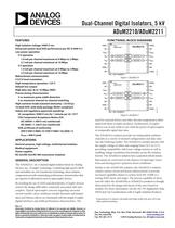
Dual-Channel Digital Isolators, 5 kV ADuM2210/ADuM2211 Rev. 0 Information furnished by Analog Devices is believed to be accurate and reliable. However, no responsibility is assumed by Analog Devices for its use, nor for any infringements of patents or other rights of third parties that may result from its use. Specifications subject to change without notice. No license is granted by implication or otherwise under any patent or patent rights of Analog Devices. Trademarks and registered trademarks are the property of their respective owners. One Technology Way, P.O. Box 9106, Norwood, MA 02062-9106, U.S.A. Tel: 781.329.4700 www.analog.com Fax: 781.461.3113 ©2010 Analog Devices, Inc. All rights reserved. FEATURES High isolation voltage: 5000 V rms Enhanced system-level ESD performance per IEC 61000-4-x Low power operation 5 V operation 1.6 mA per channel maximum at 0 Mbps to 2 Mbps 3.7 mA per channel maximum at 10 Mbps 3 V operation 1.4 mA per channel maximum at 0 Mbps to 2 Mbps 2.4 mA per channel maximum at 10 Mbps Bidirectional communication 3 V/5 V level translation High temperature operation: 125°C Default low output High data rate: dc to 10 Mbps (NRZ) Precise timing characteristics 3 ns maximum pulse width distortion 3 ns maximum channel-to-channel matching High common-mode transient immunity: >25 kV/ìs 16-lead SOIC wide body package (RoHS-compliant) Safety and regulatory approvals (pending) UL recognition: 5000 V rms for 1 minute per UL 1577 CSA Component Acceptance Notice #5A IEC 60950-1: 600 V rms (reinforced) IEC 60601-1: 250 V rms (reinforced) VDE certificate of conformity DIN V VDE V 0884-10 (VDE V 0884-10):2006-12 VIORM = 846 V peak APPLICATIONS General-purpose, high voltage, multichannel isolation Medical equipment Power supplies RS-232/RS-422/RS-485 transceiver isolation GENERAL DESCRIPTION The ADuM221x1 are 2-channel digital isolators based on Analog Devices, Inc., iCoupler® technology. Combining high speed CMOS and monolithic air core transformer technology, these isolation components provide outstanding performance characteristics that are superior to alternatives such as optocoupler devices. By avoiding the use of LEDs and photodiodes, iCoupler devices remove the design difficulties commonly associated with opto-couplers. Typical optocoupler concerns regarding uncertain current transfer ratios, nonlinear transfer functions, and temper-ature and lifetime effects are eliminated with the simple iCoupler digital interfaces and stable performance characteristics. The FUNCTIONAL BLOCK DIAGRAMS 12345678GND1NCVDD1VIAVIBNCGND1NCGND2NCVDD2VOAVOBNCNCGND2NC = NO CONNECTADuM2210161514131211109ENCODEENCODEDECODEDECODEPIN 1INDICATOR09233-001 Figure 1. ADuM2210 12345678GND1NCVDD1VOAVIBNCGND1NCGND2NCVDD2VIAVOBNCNCGND2NC = NO CONNECTADuM2211161514131211109DECODEENCODEENCODEDECODEPIN 1INDICATOR09233-002 Figure 2. ADuM2211 need for external drivers and other discrete components is elimi-nated with these iCoupler products. Furthermore, iCoupler devices run at one-tenth to one-sixth the power of optocouplers at comparable signal data rates. The ADuM221x isolators provide two independent isolation channels in a variety of channel configurations and data rates (see the Ordering Guide). The ADuM221x models operate with the supply voltage of either side ranging from 3.0 V to 5.5 V, providing compatibility with lower voltage systems as well as enabling voltage translation functionality across the isolation barrier. The ADuM221x isolators have a patented refresh feature that ensures dc correctness in the absence of input logic transi-tions and during power-up/power-down conditions. Similar to the ADuM320x isolators, the ADuM221x isolators contain various circuit and layout enhancements to provide increased capability relative to system-level IEC 61000-4-x testing (ESD, burst, and surge). The precise capability in these tests for either the ADuM320x or ADuM221x products is strongly determined by the design and layout of the user’s board or module. For more information, see the AN-793 Application Note, ESD/Latch-Up Considerations with iCoupler Isolation Products. 1 Protected by U.S. Patents 5,952,849; 6,873,065; 6,903,578; and 7,075,329. Other patents pending.
Open the catalog to page 1
ADuM2210/ADuM2211 Rev. 0 | Page 3 of 20 SPECIFICATIONS ELECTRICAL CHARACTERISTICS—5 V OPERATION All voltages are relative to their respective ground. 4.5 V VDD1 5.5 V, 4.5 V VDD2 5.5 V. All minimum/maximum specifications apply over the entire recommended operation range, unless otherwise noted. All typical specifications are at TA = 25°C, VDD1 = VDD2 = 5 V. Table 1. Parameter Symbol Min Typ Max Unit Test Conditions DC SPECIFICATIONS Input Supply Current, per Channel, Quiescent IDDI (Q) 0.4 0.8 mA Output Supply Current, per Channel, Quiescent IDDO (Q) 0.5 0.6 mA ADuM2210, Total Supply Current,...
Open the catalog to page 3
ADuM2210/ADuM2211 Rev. 0 | Page 4 of 20 Parameter Symbol Min Typ Max Unit Test Conditions ADuM221xTR Minimum Pulse Width2 PW 100 ns CL = 15 pF, CMOS signal levels Maximum Data Rate3 10 Mbps CL = 15 pF, CMOS signal levels Propagation Delay4 tPHL, tPLH 20 50 ns CL = 15 pF, CMOS signal levels Pulse Width Distortion, |tPLH - tPHL|4 PWD 3 ns CL = 15 pF, CMOS signal levels Change vs. Temperature 5 ps/°C CL = 15 pF, CMOS signal levels Propagation Delay Skew5 tPSK 15 ns CL = 15 pF, CMOS signal levels Channel-to-Channel Matching, Codirectional Channels6 tPSKCD 3 ns CL = 15 pF, CMOS signal levels Channel-to-Channel...
Open the catalog to page 4
ADuM2210/ADuM2211 Rev. 0 | Page 5 of 20 ELECTRICAL CHARACTERISTICS—3 V OPERATION All voltages are relative to their respective ground. 3.0 V VDD1 3.6 V, 3.0 V VDD2 3.6 V. All minimum/maximum specifications apply over the entire recommended operation range, unless otherwise noted. All typical specifications are at TA = 25°C, VDD1 = VDD2 = 3.0 V. Table 2. Parameter Symbol Min Typ Max Unit Test Conditions DC SPECIFICATIONS Input Supply Current, per Channel, Quiescent IDDI (Q) 0.3 0.5 mA Output Supply Current, per Channel, Quiescent IDDO (Q) 0.3 0.5 mA ADuM2210, Total Supply Current, Two Channels1...
Open the catalog to page 5All Analog Devices catalogs and technical brochures
 HMC722LP3E
8 Pages
 Isolated Sigma-Delta Modulator
17 Pages
 HMC853 Data Sheet
10 Pages
 AN-1084
8 Pages
 AN-1091
2 Pages
 AN_737
8 Pages
 AN-0982
4 Pages
 ADF7024
24 Pages
 AD9915
48 Pages
 AD9914
48 Pages
 ADRF6612
59 Pages
 ADRF6820
48 Pages
 ADL5246
32 Pages
 ADA4961
22 Pages
 AN-1141
8 Pages
 AN-698
36 Pages
 Temperature Sensors
2 Pages
 Reference Circuits
8 Pages
 Precision ADCs
16 Pages
 ADR02ACHIPS: ADR02ACHIPS
8 Pages
 AD9364 RF Agile Transceiver
32 Pages
 Digital Temperature Sensors
2 Pages
 Digital to Analog Converter ICs
12 Pages
 AD1836A: Multichannel 96 kHz Codec
24 Pages


Archived catalogs
 Zero-Drift Amplifiers
2 Pages
 Powering ADI Components
8 Pages


- Ethernet switch
- Industrial network switch
- Acceleration sensor
- Unmanaged switch
- Analog Devices motor controller
- Triaxial acceleration sensor
- DC motor controller
- Data acquisition unit
- Analog Devices stepper motor controller
- Industrial converter
- Ethernet transceiver
- Processor
- High-voltage amplifier
- Low-noise amplifier
- Multiplexer
- Compact motor controller
- Gyroscope
- Closed-loop motor controller
- Digital converter