
- Catalogs
- Analog Devices
- ADSP-BF512/ADSP-BF514/ADSP-BF514F16/ADSP-BF516/ADSP-BF518/ADSP-BF518F16 Blackfin Embedded Processor


- Products
- Catalogs
- News & Trends
- Exhibitions
ADSP-BF512/ADSP-BF514/ADSP-BF514F16/ADSP-BF516/ADSP-BF518/ADSP-BF518F16 Blackfin Embedded Processor

ADSP-BF512/ADSP-BF514/ADSP-BF514F16/ADSP-BF516/ADSP-BF518/ADSP-BF518F16 Blackfin Embedded Processor
The Blackfin processors deliver up to 400 MHz performance with two 16-bit MACs, two 40-bit ALUs, and four 8-bit video ALUs. They support a RISC-like register and instruction model, advanced debugging, and various operating voltages. They are automotive-qualified and available in 168-ball CSP_BGA or 176-lead LQFP_EP packages.
These processors include 116K bytes of on-chip memory, an external memory controller for SDRAM, and optional 16M bit SPI flash. They offer flexible booting options and code security with Lockbox technology.
Key peripherals include IEEE 802.3-compliant Ethernet MAC, parallel peripheral interface, dual-channel synchronous serial ports, multiple DMAs, SPI interfaces, UARTs, and a real-time clock. Debug/JTAG interface and on-chip PLL are also featured.
The ADSP-BF51x series are part of the Blackfin family, combining signal processing capabilities with a RISC-like instruction set and multimedia support. They are code compatible with other Blackfin processors and integrate a rich set of peripherals and memory for next-generation applications.
Designed for low power consumption, these processors feature dynamic power management to adjust voltage and frequency, enhancing battery life for portable devices.
The processors support network-connected applications with standard interfaces and a high-performance core, reducing the need for external components.
The core includes two 16-bit multipliers, two 40-bit accumulators, and four video ALUs. It supports 8-, 16-, or 32-bit data operations and features a modified Harvard architecture with hierarchical memory.
Level 1 (L1) memories operate at full processor speed, with instruction memory, data memories, and a scratchpad for stack and local variables. The MMU provides memory protection.
The architecture supports user, supervisor, and emulation modes, with user mode providing restricted access to system resources.
The instruction set is optimized for code density, with 16-bit opcodes for common instructions and 32-bit opcodes for complex DSP instructions.
The Blackfin processor supports parallel execution of two 16-bit instructions, optimizing resource usage per cycle. Its assembly language uses algebraic syntax for readability and is optimized for C/C++ compilers, enhancing software efficiency.
The ADSP-BF51x processors feature a unified 4GB address space with 32-bit addresses, encompassing internal memory, external memory, and I/O control registers. The memory hierarchy balances cost and performance with fast on-chip memory and larger off-chip systems.
The processors include three on-chip memory blocks: L1 instruction memory (48KB SRAM), L1 data memory (up to 64KB), and a 4KB scratchpad SRAM.
Accessed via the EBIU, the external memory supports SDRAM and up to four banks of asynchronous memory devices.
The ADSP-BF51xF processors include an SPI flash memory with 16Mb capacity, supporting fast erase and byte-program capabilities, and software write protection.
The processors feature 64Kb of non-volatile OTP memory for secure data storage.
All resources are mapped through a flat 32-bit address space, with control registers for on-chip I/O devices mapped into memory-mapped registers (MMRs).
The event controller manages asynchronous and synchronous events, supporting nesting and prioritization.
The processors have multiple DMA channels for automated data transfers, supporting 1-D and 2-D transfers.
The ADSP-BF51x processors include a variety of peripherals connected via high bandwidth buses, supporting network communication, serial and parallel ports, and power management functions.
The RTC provides digital watch features such as current time, stopwatch, and alarm, powered by a 32.768 kHz crystal.
A 32-bit timer used for implementing a software watchdog function to reset the processor in case of software failure.
The ADSP-BF51x processors include nine programmable timers for various functions, including PWM generation, pulse width measurement, and synchronization with external clocks.
A programmable unit for generating PWM waveforms for motor control.
A 32-bit counter for sensing quadrature or binary codes.
Two dual-channel synchronous serial ports (SPORT0 and SPORT1) for serial and multiprocessor communications.
Two SPI-compatible ports for communication with multiple devices.
Two full-duplex UART ports compatible with PC-standard UARTs.
A module compatible with the I2C bus standard for control data exchange.
An interface for MMC, SD, SDIO cards, and CE-ATA hard drives.
Provides network connectivity with support for 10-BaseT and 100-BaseT operations.
Hardware support for precision clock synchronization.
The processors have multiple ports and 40 GPIO signals for peripheral signal grouping and control.
The ADSP-BF51x processors feature a PPI that connects to parallel ADCs, DACs, and video encoders/decoders.
This security system combines hardware and software to offer features like OTP memory, unique chip ID, code authentication, and secure operation modes.
The processors offer four operating modes: Full-On, Active, Sleep, and Deep Sleep, each with different power/performance profiles.
The processors support up to six power domains, allowing for dynamic power management without affecting RTC or I/O devices.
An external voltage regulator powers the VDDINT domain.
The processors can be clocked by an external crystal or clock oscillator.
The maximum CCLK frequency is influenced by the part's speed grade and the applied VDDINT voltage.
The processor supports various booting modes, categorized into master and slave modes.
The Blackfin processor family uses an algebraic syntax for its assembly language, optimized for small memory size and efficient C/C++ compilation.
Analog Devices provides software and hardware development tools, including CrossCore Embedded Studio and VisualDSP++ IDEs.
Analog Devices offers emulators for embedded system testing and debugging.
Further resources include hardware references, programming references, and anomaly lists for the ADSP-BF51x Blackfin processors.
The document provides technical specifications and guidelines for Analog Devices products, focusing on signal chains, secure technology, and processor signal descriptions.
The Circuits from the Lab site offers graphical circuit block diagrams for various applications.
Analog Devices provides a disclaimer regarding the security of its Lockbox Secure Technology.
The document lists signal definitions for processors, noting that some signals have dual functions.
The document outlines operating conditions for various supply voltages and junction temperatures for different models.
Timing requirements for processor clocks are detailed.
The document outlines the electrical characteristics of the ADSP-BF51x series processors.
The document provides detailed procedures for calculating power dissipation.
Reliability characteristics are defined by JEDEC standards.
The document advises on the maximum duty cycle for input transient voltage.
Several tables provide detailed data on static and dynamic current consumption.
The document emphasizes the importance of adhering to specified voltage and frequency ranges.
The document outlines the timing requirements and switching characteristics for the SDRAM interface.
This section describes the timing for external DMA requests.
The timing for the parallel peripheral interface (PPI) is detailed.
Timing requirements for the RSI controller are provided.
The document provides timing details for serial ports.
Master and slave timing for the SPI port is described.
Timing for general-purpose ports is outlined.
Details on timer clock timing and cycle timing are provided.
The document specifies timing requirements for up/down counters and rotary encoders.
This document provides specifications for various models of the ADSP-BF512, BF514, BF514F16, BF516, BF518, and BF518F16 processors by Analog Devices.
- Temperature Range: Models are available for both commercial (0ºC to +70ºC) and industrial (-40ºC to +85ºC) temperature ranges.
- Processor Instruction Rate: Maximum rates are either 300 MHz or 400 MHz, depending on the model.
- Flash Memory: Some models include 16M bit flash memory, while others do not have integrated flash memory.
- Package Description: Two main package types are used: 176-Lead LQFP_EP SQ-176-2 and 168-Ball CSP_BGA BC-168-1.
- ADSP-BF512: Available in both LQFP and CSP_BGA packages, with 300 MHz and 400 MHz options.
- ADSP-BF514: Similar to BF512, with additional models featuring 16M bit flash memory.
- ADSP-BF516: Offers both 300 MHz and 400 MHz options, available in both package types.
- ADSP-BF518: Includes models with 16M bit flash memory, available in both package types.
- All models are RoHS compliant.
- Ambient temperature is referenced, but junction temperature specifications are detailed on page 22.
Catalog excerpts

Blackfin Embedded Processor ADSP-BF512/BF514/BF514F16/BF516/BF518/BF518F16 FEATURES Up to 400 MHz high performance Blackfin processor Two 16-bit MACs, two 40-bit ALUs, four 8-bit video ALUs, 40-bit shifter RISC-like register and instruction model for ease of programming and compiler-friendly support Advanced debug, trace, and performance monitoring Wide range of operating voltages. See Operating Conditions on Page 22 Qualified for Automotive Applications. See Automotive Products on Page 67 168-ball CSP_BGA or 176-lead LQFP_EP (with exposed pad) IEEE 802.3-compliant 10/100 Ethernet MAC with IEEE 1588 support (ADSP-BF518/ADSP-BF518F16 only) Parallel peripheral interface (PPI), supporting ITU-R 656 video data formats 2 dual-channel, full-duplex synchronous serial ports (SPORTs), supporting 8 stereo I2S channels 12 peripheral DMAs, 2 mastered by the Ethernet MAC 2 memory-to-memory DMAs with external request lines Event handler with 56 interrupt inputs 2 serial peripheral interfaces (SPI) Removable storage interface (RSI) controller for MMC, SD, SDIO, and CE-ATA 2 UARTs with IrDA support 2-wire interface (TWI) controller Eight 32-bit timers/counters with PWM support 3-phase 16-bit center-based PWM unit 32-bit general-purpose counter Real-time clock (RTC) and watchdog timer 32-bit core timer 40 general-purpose I/Os (GPIOs) Debug/JTAG interface On-chip PLL capable of frequency multiplication MEMORY 116K bytes of on-chip memory External memory controller with glueless support for SDRAM and asynchronous 8-bit and 16-bit memories Optional 16M bit SPI flash with boot option Flexible booting options from internal SPI flash, OTP memory, external SPI/parallel memories, or from SPI/UART host devices Code security with Lockbox secure technology One-time-programmable (OTP) memory Memory management unit providing memory protection WATCHDOG TIMER PERIPHERAL ACCESS BUS COUNTER JTAG TEST AND EMULATION INTERRUPT CONTROLLER EXTERNAL PORT FLASH, SDRAM CONTROL Figure 1. Functional Block Diagram Blackfin and the Blackfin logo are registered trademarks of Analog Devices, Inc. Document Feedback Information furnished by Analog Devices is believed to be accurate and reliable. However, no responsibility is assumed by Analog Devices for its use, nor for any infringements of patents or other rights of third parties that may result from its use. Specifications subject to change without notice. No license is granted by implication or otherwise under any patent or patent rights of Analog Devices. Trademarks and registered trademarks are the property of their respective owners. One Technology Way, P.O. Box 9106, Norwood, MA 02062-9106 U.S.A. Tel: 781.329.4700 ©2014 Analog Devices, Inc. All rights reserved. Technical Support www.analog.com
Open the catalog to page 1
ADSP-BF512/BF514/BF514F16/BF516/BF518/BF518F16 GENERAL DESCRIPTION The ADSP-BF512/ADSP-BF514/ADSP-BF514F16/ADSPBF516/ADSP-BF518/ADSP-BF518F16 processors are members of the Blackfin® family of products, incorporating the Analog Devices/Intel Micro Signal Architecture (MSA). Blackfin processors combine a dual-MAC state-of-the-art signal processing engine, the advantages of a clean, orthogonal RISC-like microprocessor instruction set, and single-instruction, multiple-data (SIMD) multimedia capabilities into a single instruction-set architecture. The processors are completely code compatible with...
Open the catalog to page 3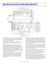
ADSP-BF512/BF514/BF514F16/BF516/BF518/BF518F16 ADDRESS ARITHMETIC UNIT DECODE BARREL SHIFTER LOOP BUFFER CONTROL UNIT 32 DATA ARITHMETIC UNIT Figure 2. Blackfin Processor Core For certain instructions, two 16-bit ALU operations can be performed simultaneously on register pairs (a 16-bit high half and 16-bit low half of a compute register). If the second ALU is used, quad 16-bit operations are possible. The 40-bit shifter can perform shifts and rotates and is used to support normalization, field extract, and field deposit instructions. The program sequencer controls the flow of instruction execution,...
Open the catalog to page 4
ADSP-BF512/BF514/BF514F16/BF516/BF518/BF518F16 The on-chip L1 memory system is the highest-performance memory available to the Blackfin processor. The off-chip memory system, accessed through the external bus interface unit (EBIU), provides expansion with SDRAM, flash memory, and SRAM, optionally accessing up to 132M bytes of physical memory. instruction can be issued in parallel with two 16-bit instructions, allowing the programmer to use many of the core resources in a single instruction cycle. The Blackfin processor assembly language uses an algebraic syntax for ease of coding and readability....
Open the catalog to page 5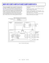
ADSP-BF512/BF514/BF514F16/BF516/BF518/BF518F16 • Serial Interface Architecture—SPI compatible with Mode 0 and Mode 3 The processors internally connect to the flash memory die with the SPI0SCK, SPI0SEL4 or PH8, SPI0MOSI, and SPI0MISO signals similar to an external SPI flash (for signal descriptions, see Table 2). To further provide a secure processing environment, these internally connected signals are not exposed outside of the package. For this reason, programming the ADSP-BF51xF flash memory is performed by running code on the processor and cannot be programmed from external signals. Data transfers...
Open the catalog to page 6
ADSP-BF512/BF514/BF514F16/BF516/BF518/BF518F16 Table 2. Internal Flash Memory Signal Descriptions Symbol Serial Clock Provides the timing of the serial interface. Commands, addresses, or input data are latched on the rising edge of the clock input, while output data is shifted out on the falling edge of the clock input. Serial Data Input Transfers commands, addresses, or data serially into the device. Inputs are latched on the rising edge of the serial clock. Serial Data Output Transfers data serially out of the device. Data is shifted out on the falling edge of the serial clock. Flash busy status...
Open the catalog to page 7
ADSP-BF512/BF514/BF514F16/BF516/BF518/BF518F16 (EVT), and lists their priorities are described in the ADSP-BF51x Blackfin Processor Hardware Reference Manual “System Interrupts” chapter. System Interrupt Controller (SIC) The system interrupt controller provides the mapping and routing of events from the many peripheral interrupt sources to the prioritized general-purpose interrupt inputs of the CEC. Although the processors provide a default mapping, the user can alter the mappings and priorities of interrupt events by writing the appropriate values into the interrupt assignment registers (SIC_IARx)....
Open the catalog to page 8All Analog Devices catalogs and technical brochures
 HMC722LP3E
8 Pages
 Isolated Sigma-Delta Modulator
17 Pages
 HMC853 Data Sheet
10 Pages
 AN-1084
8 Pages
 AN-1091
2 Pages
 AN_737
8 Pages
 AN-0982
4 Pages
 ADF7024
24 Pages
 AD9915
48 Pages
 AD9914
48 Pages
 ADRF6612
59 Pages
 ADRF6820
48 Pages
 ADL5246
32 Pages
 ADA4961
22 Pages
 AN-1141
8 Pages
 AN-698
36 Pages
 Temperature Sensors
2 Pages
 Reference Circuits
8 Pages
 Precision ADCs
16 Pages
 ADR02ACHIPS: ADR02ACHIPS
8 Pages
 AD9364 RF Agile Transceiver
32 Pages
 Digital Temperature Sensors
2 Pages
 Digital to Analog Converter ICs
12 Pages
 AD1836A: Multichannel 96 kHz Codec
24 Pages













































Archived catalogs
 Zero-Drift Amplifiers
2 Pages
 Powering ADI Components
8 Pages








- Ethernet switch
- Industrial network switch
- Acceleration sensor
- Unmanaged switch
- Analog Devices motor controller
- Transceiver module
- Triaxial acceleration sensor
- DC motor controller
- Data acquisition unit
- Analog Devices stepper motor controller
- Industrial converter
- Ethernet transceiver
- High-voltage amplifier
- Low-noise amplifier
- Multiplexer
- Compact motor controller
- Digital converter
- Closed-loop motor controller
- Digital motor controller