- Catalogs
- Analog Devices
- ADM1085/ADM1086/ADM1087: Simple Sequencers® in 6-Lead SC70
ADM1085/ADM1086/ADM1087: Simple Sequencers® in 6-Lead SC70
1 /16Pages

ADM1085/ADM1086/ADM1087: Simple Sequencers® in 6-Lead SC70
1 /16Pages
Catalog excerpts

Data Sheet FEATURES FUNCTIONAL BLOCK DIAGRAMS VCC CAPACITOR ADJUSTABLE DELAY CAPACITOR ADJUSTABLE DELAY APPLICATIONS Desktop/notebook computers, servers Low power portable equipment Routers Base stations Line cards Graphics cards Provide programmable time delays between enable signals Can be cascaded with power modules for multiple supply sequencing Power supply monitoring from 0.6 V Output stages High voltage (up to 22 V) open-drain output (ADM1085/ADM1087) Push-pull output (ADM1086) Capacitor-adjustable time delays High voltage (up to 22 V) enable and VIN inputs Low power consumption (15 μA) Specified over –40°C to +125°C temperature range 6-lead SC70 package GENERAL DESCRIPTION The ADM1085/ADM1086/ADM1087 are simple sequencing circuits that provide a time delay between the enabling of voltage regulators and/or dc-dc converters at power-up in multiple supply systems. When the output voltage of the first power module reaches a preset threshold, a time delay is initiated before an enable signal allows subsequent regulators to power up. Any number of these devices can be cascaded with regulators to allow sequencing of multiple power supplies. Threshold levels can be set with a pair of external resistors in a voltage divider configuration. With appropriate resistor values, the threshold can be adjusted to monitor voltages as low as 0.6 V. The ADM1086 has a push-pull output stage, with active high (ENOUT). The ADM1085 has an active-high (ENOUT) logic output; the ADM1087 has an active-low (ENOUT) output. Both the ADM1085 and ADM1087 have open-drain output stages that can be pulled up to voltage levels as high as 22 V through an external resistor. This level-shifting property ensures compatibility with enable input logic levels of different regulators and converters. Rev. B All four models have a dedicated enable input pin that allows the output signal to the regulator to be controlled externally. This is an active high input (ENIN) for the ADM1085 and ADM1086, and an active low input (ENIN) for the ADM1087. The Simple Sequencers are specified over the extended −40°C to +125°C temperature range. With low current consumption of 15 μA (typical) and 6-lead SC70 packaging, the parts are suitable for low-power portable applications. Table 1. Selection Table Output Stage ENOUT ENOUT Enable Input Document Feedback Information furnished by Analog Devices is believed to be accurate and reliable. However, no responsibility is assumed by Analog Devices for its use, nor for any infringements of patents or other rights of third parties that may result from its use. Specifications subject to change without notice. No license is granted by implication or otherwise under any patent or patent rights of Analog Devices. Trademarks and registered trademarks are the property of their respective owners. One Technology Way, P.O. Box 9106, Norwood, MA 02062-9106, U.S.A. Tel: 781.329.4700 ©2004–2014 Analog Devices, Inc. All rights reserved. Technical Support www.analog.com
Open the catalog to page 1
Data Sheet
Open the catalog to page 2
Data Sheet SPECIFICATIONS VCC = full operating range, TA = −40°C to +125°C, unless otherwise noted. Table 2. Parameter SUPPLY VCC Operating Voltage Range VIN Operating Voltage Range Supply Current VIN Rising Threshold, VTH_RISING VIN Falling Threshold, VTH_FALLING VIN Hysteresis VIN to ENOUT/ENOUT Delay VIN Rising VIN Falling VIN Leakage Current CEXT Charge Current Threshold Temperature Coefficient ENIN/ENIN to ENOUT/ENOUT Propagation Delay ENIN/ENIN Voltage Low ENIN/ENIN Voltage High ENIN/ENIN Leakage Current ENOUT/ENOUT Voltage Low ENOUT/ENOUT Voltage High (ADM1086) ENOUT/ENOUT Open-Drain Output...
Open the catalog to page 3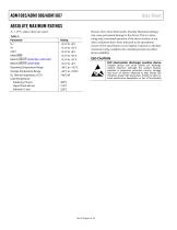
Data Sheet Stresses above those listed under Absolute Maximum Ratings may cause permanent damage to the device. This is a stress rating only; functional operation of the device at these or any other conditions above those indicated in the operational section of this specification is not implied. Exposure to absolute maximum rating conditions for extended periods may affect device reliability. ESD (electrostatic discharge) sensitive device. Charged devices and circuit boards can discharge without detection. Although this product features patented or proprietary protection circuitry, damage may...
Open the catalog to page 4
Data Sheet PIN CONFIGURATION AND FUNCTION DESCRIPTIONS 4 ENOUT/ENOUT TOP VIEW (Not to Scale) Table 4. Pin Function Descriptions Pin No. 1 Mnemonic ENIN, ENIN ENOUT, ENOUT Description Enable Input. Controls the status of the enable output. Active high for ADM1085/ADM1086. Active low for ADM1087. Ground. Input for the Monitored Voltage Signal. Can be biased via a voltage divider resistor network to customize the effective input threshold. Can precisely monitor an analog power supply output signal and detect when it has powered up. The voltage applied at this pin is compared with a 0.6 V on-chip...
Open the catalog to page 5
Data Sheet TYPICAL PERFORMANCE CHARACTERISTICS 700 Figure 6. VIN Leakage Current vs. VIN Voltage Figure 4. Supply Current vs. Supply Voltage Figure 7. VIN Leakage Current vs. VCC Voltage Figure 3. VIN Threshold vs. Temperature OUTPUT SINK CURRENT (mA) Figure 5. Supply Current vs. VIN Voltage Figure 8. Output Voltage vs. Output Sink Current VTRIP RISING
Open the catalog to page 6
Data Sheet Figure 9. Output Low Voltage vs. Supply Voltage Figure 12. ENIN/ ENIN Leakage Current vs. ENIN/ ENIN Voltage Figure 10. VCC Falling Propagation Delay vs. Temperature Figure 13. ENIN/ ENIN Leakage Current vs. VCC Voltage Figure 14. CEXT Capacitance vs. Timeout Delay Figure 11. Output Fall Time vs. Supply Voltage
Open the catalog to page 7
Figure 17. Maximum VIN Transient Duration vs. Comparator Overdrive Figure 15. CEXT Charge Current vs. Temperature Figure 16. VIN to ENOUT/ ENOUT Propagation Delay (CEXT Floating) vs. Temperature
Open the catalog to page 8
Data Sheet CIRCUIT INFORMATION TIMING CHARACTERISTICS AND TRUTH TABLES The enable outputs of the ADM1085/ADM1086/ADM1087 are related to the VIN and enable inputs by a simple AND function. The enable output is asserted only if the enable input is asserted and the voltage at VIN is above VTH_RISING, with the time delay elapsed. Table 5 and Table 6 show the enable output logic states for different VIN/enable input combinations when the capacitor delay has elapsed. The timing diagrams in Figure 18 and Figure 19 give a graphical representation of how the ADM1085/ADM1086/ ADM1087 enable outputs respond...
Open the catalog to page 9All Analog Devices catalogs and technical brochures
 HMC722LP3E
8 Pages
 Isolated Sigma-Delta Modulator
17 Pages
 HMC853 Data Sheet
10 Pages
 AN-1084
8 Pages
 AN-1091
2 Pages
 AN_737
8 Pages
 AN-0982
4 Pages
 ADF7024
24 Pages
 AD9915
48 Pages
 AD9914
48 Pages
 ADRF6612
59 Pages
 ADRF6820
48 Pages
 ADL5246
32 Pages
 ADA4961
22 Pages
 AN-1141
8 Pages
 AN-698
36 Pages
 Temperature Sensors
2 Pages
 Reference Circuits
8 Pages
 Precision ADCs
16 Pages
 ADR02ACHIPS: ADR02ACHIPS
8 Pages
 AD9364 RF Agile Transceiver
32 Pages
 Digital Temperature Sensors
2 Pages
 Digital to Analog Converter ICs
12 Pages
 AD1836A: Multichannel 96 kHz Codec
24 Pages


Archived catalogs
 Zero-Drift Amplifiers
2 Pages
 Powering ADI Components
8 Pages


- Ethernet switch
- Industrial network switch
- Acceleration sensor
- Unmanaged switch
- Transceiver module
- Analog Devices motor controller
- Triaxial acceleration sensor
- DC motor controller
- Data acquisition unit
- Analog Devices stepper motor controller
- Industrial converter
- Ethernet transceiver
- Processor
- High-voltage amplifier
- Low-noise amplifier
- Multiplexer
- Compact motor controller
- Gyroscope
- Closed-loop motor controller
- Digital converter