
- Catalogs
- Analog Devices
- ADA4571: Integrated AMR Angle Sensor and Signal Conditioner Data Sheet


- Products
- Catalogs
- News & Trends
- Exhibitions
ADA4571: Integrated AMR Angle Sensor and Signal Conditioner Data Sheet

ADA4571: Integrated AMR Angle Sensor and Signal Conditioner Data Sheet
The ADA4571 is a high precision 180° angle sensor with a maximum angular error of 0.5°. It provides analog sine and cosine outputs, low thermal and lifetime drift, and is capable of driving SAR or Σ-Δ ADCs. It includes MR bridge temperature compensation, operates within a temperature range of −40°C to +150°C, and is EMI resistant with fault diagnostics. The device operates with a VDD from 2.7 V to 5.5 V and is qualified for automotive applications, available in an 8-lead SOIC package.
The sensor is suitable for absolute position measurement, brushless DC motor control, actuator control, contactless angular measurement, and magnetic angular position sensing.
The ADA4571 integrates an AMR sensor with signal conditioning amplifiers and ADC drivers, producing two analog outputs indicating the angular position of a magnetic field. It consists of an AMR sensor and a fixed gain instrumentation amplifier, delivering amplified cosine and sine output signals. The sensor includes two Wheatstone bridges at a 45° angle to each other, providing sinusoidal output signals independent of the z-direction placement.
Magnetic Characteristics: The sensor requires a magnetic field strength of 25 kA/m in the x-y plane for minimal error. It supports a maximum magnetic field rotational frequency of 50,000 rpm.
Electrical Characteristics: The ADA4571 operates over a supply voltage range of 2.7 V to 5.5 V, with a quiescent supply current of 3.5 to 6.5 mA. It features a power-up time of 150 µs to reach 98% of the desired output level.
The ADA4571 offers contactless angular measurement, measures magnetic field direction, and has minimal sensitivity to air gap variations. It provides excellent accuracy even for weak saturation fields, with minimal thermal and lifetime drift, negligible hysteresis, and is a single-chip solution.
The ADA4571 has specific limits for operating and storage temperatures, supply voltage, and short-circuit durations. It can operate between -40°C to +150°C and be stored between -65°C to +150°C. The supply voltage should be between -0.3 V to +6 V. The device can withstand indefinite short-circuit durations to GND or VDD. ESD ratings are provided for different models, with the Human Body Model rated at 4000 V.
The thermal resistance for an 8-Lead SOIC package is specified as 120 °C/W, indicating the heat dissipation capability of the device.
The ADA4571 features eight pins with specific functions, including Gain Control Mode Enable, Analog Cosine and Sine Outputs, Ground, Temperature Output, Supply Pin, and Power-Down Pin.
Various figures illustrate the device's performance under different conditions, such as raw output waveforms, error waveforms after offset correction, and dynamic angular errors at different supply voltages and temperatures.
Key terms are defined, including reference position and angle errors, output amplitude synchronism error, uncorrected and single point calibration angular errors, dynamic angular error, and phase error.
The ADA4571 is an AMR sensor with integrated signal conditioning amplifiers and ADC drivers, producing sine and cosine outputs to indicate the angular position of a magnetic field. It features precision, low noise, zero drift amplifiers with a proprietary chopping technique for high precision sensing applications.
The sensor is designed for use with a separate processing IC or ECU. It is ratiometric, minimizing signal dependency on supply voltage changes. Angle calculation is performed using the arctangent2 function. Connection to an ECU should minimize PCB trace lengths and include shielding and matched load components for best accuracy.
Gain control mode compensates for temperature variations, enhancing output voltage levels. Power-down mode reduces power consumption by setting output pins to high impedance.
Catalog excerpts
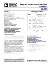
FUNCTIONAL BLOCK DIAGRAM VDD High precision 180° angle sensor Maximum angular error of 0.5° Analog sine and cosine outputs Ratiometric output voltages Low thermal and lifetime drift SAR or Σ-Δ analog-to-digital converter (ADC) drive capable Magnetoresistive (MR) bridge temperature compensation mode Temperature range: −40°C to +150°C EMI resistant Fault diagnostics VDD from 2.7 V to 5.5 V Minimum phase delay Qualified for automotive applications Available in an 8-lead SOIC package TEMPERATURE SENSOR BRIDGE DRIVER Absolute position measurement (linear and angle) Brushless dc motor control and positioning Actuator control and positioning Contactless angular measurement and detection Magnetic angular position sensing FAULT DETECTION Data Sheet Integrated AMR Angle Sensor and Signal Conditioner ADA4571 GENERAL DESCRIPTION The ADA4571 is an anisotropic magnetoresistive (AMR) sensor with integrated signal conditioning amplifiers and ADC drivers. The ADA4571 produces two analog outputs that indicate the angular position of the surrounding magnetic field. The ADA4571 consists of two die within one package, an AMR sensor, and a fixed gain (G = 40 nominally) instrumentation amplifier. The ADA4571 delivers clean and amplified cosine and sine output signals related to the angle of a rotating magnetic field. The output voltage range is ratiometric to the supply voltage. The sensor contains two Wheatstone bridges, at a relative angle of 45° to one another. A rotating magnetic field in the x-y sensor plane delivers two sinusoidal output signals with the double frequency of the angle (α) between sensor and magnetic field direction. Within a homogeneous field in the x-y plane, the output signals are independent of the physical placement in the z direction (air gap). COMPANION PRODUCTS ADCs: AD7265, AD7266, AD7866, AD7902 Microconverter: ADuCM360 Current Sense Amplifier: AD8418A Voltage Regulator Design Tool: ADIsimPower Additional companion products on the ADA4571 product page Contactless angular measurement. Measures magnetic field direction rather than field intensity. Minimum sensitivity to air gap variations. Large working distance. Excellent accuracy, even for weak saturation fields. Minimal thermal and lifetime drift. Negligible hysteresis. Single chip solution. The ADA4571 is available in an 8-lead SOIC package. Document Feedback Information furnished by Analog Devices is believed to be accurate and reliable. However, no responsibility is assumed by Analog Devices for its use, nor for any infringements of patents or other rights of third parties that may result from its use. Specifications subject to change without notice. No license is granted by implication or otherwise under any patent or patent rights of Analog Devices. Trademarks and registered trademarks are the property of their respective owners. One Technology Way, P.O. Box 9106, Norwood, MA 02062-9106, U.S.A. Tel: 781.329.4700 ©2014 Analog Devices, Inc. All rights reserved. Technical Support www.analog.com
Open the catalog to page 1
Data Sheet REVISION HISTORY 10/14—Revision 0: Initial Version
Open the catalog to page 2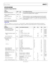
Data Sheet SPECIFICATIONS MAGNETIC CHARACTERISTICS Table 1. Parameter Magnetic Field Strength, HEXT Maximum Magnetic Field Rotational Frequency Reference Position Error Reference Angle Error Test Conditions/Comments The stimulating magnetic field in the x-y sensor plane necessary to ensure the minimum error as specified in Table 1 and Table 2 Reference position for y = 0 µm is the straight connection line of Pin 2 and Pin 7; the x = 0 µm position is referred to the middle distance of the package top Reference position for angle Φ = 0° is parallel to the straight connection line of Pin 2 and Pin...
Open the catalog to page 3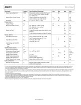
ADA4571 Parameter Power Supply Rejection3 Output Short-Circuit Current Sensitivity POWER SUPPLY Supply Voltage Quiescent Supply Current Power-Up Time DIGITAL INPUTS Input Bias Current (GC) Input Bias Current (PD) Input Voltage (GC and PD) High Low TEMPERATURE SENSOR Error Over Temperature Temperature Voltage Range Temperature Coefficient VTEMP Output Voltage VTEMP Output Impedance VTEMP Load Capacitance VTEMP Short-Circuit Current LOAD CAPACITOR External Load Capacitance Data Sheet Symbol PSRR ISC SEN VDD ISY IB_GC IB_PD Test Conditions/Comments Measured as output variation from VDD/2, VDD =...
Open the catalog to page 4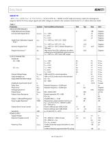
Data Sheet ADA4571B −40°C ≤ TA ≤ +125°C, VDD = 2.7 V to 5.5 V, CL = 10 nF to GND, RL = 200 kΩ to GND; angle inaccuracies referred to homogenous magnetic field of 25 kA/m; output signals and offset voltages are related to the common-mode level of VDD/2, unless otherwise stated. Table 3. Parameter ANGULAR PERFORMANCE Angle Measurement Range Uncorrected Angular Error1 Test Conditions/Comments Output Voltage Range Output Voltage Low Output Referred Offset Voltage Amplitude Synchronism Error6 Delay Time Phase Error7 Orthogonality Error3 Output Noise Output Series Resistance k tDEL ΦERR OE VNOISE RO...
Open the catalog to page 5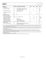
ADA4571 Parameter DIGITAL INPUTS Input Bias Current (GC) Input Bias Current (PD) Input Voltage (GC and PD) High Low TEMPERATURE SENSOR Error Over Temperature Temperature Voltage Range Temperature Coefficient VTEMP Output Voltage VTEMP Output Impedance VTEMP Load Capacitance VTEMP Short-Circuit Current LOAD CAPACITOR External Load Capacitance Data Sheet Symbol Test Conditions/Comments For GC mode control pin, GC = GND For GC mode control pin, GC = VDD For PD pin, PD = GND For PD pin, PD = VDD TA = 25°C Buffered output Optional load capacitance Short-circuit to VDD or GND Between VSIN to GND and...
Open the catalog to page 6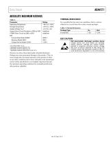
Data Sheet ABSOLUTE MAXIMUM RATINGS Operating Temperature Storage Temperature Output Short-Circuit Duration to GND orVDD Human Body Model (HBM)2 Charge Device Model (CDM)4 4 Applicable standard: ESDA/JEDEC JS-001 -2011. Stresses at or above those listed under Absolute Maximum Ratings may cause permanent damage to the product. This is a stress rating only; functional operation of the product at these or any other conditions above those indicated in the operational section of this specification is not implied. Operation beyond the maximum operating conditions for extended periods may affect product...
Open the catalog to page 7All Analog Devices catalogs and technical brochures
 HMC722LP3E
8 Pages
 Isolated Sigma-Delta Modulator
17 Pages
 HMC853 Data Sheet
10 Pages
 AN-1084
8 Pages
 AN-1091
2 Pages
 AN_737
8 Pages
 AN-0982
4 Pages
 ADF7024
24 Pages
 AD9915
48 Pages
 AD9914
48 Pages
 ADRF6612
59 Pages
 ADRF6820
48 Pages
 ADL5246
32 Pages
 ADA4961
22 Pages
 AN-1141
8 Pages
 AN-698
36 Pages
 Temperature Sensors
2 Pages
 Reference Circuits
8 Pages
 Precision ADCs
16 Pages
 ADR02ACHIPS: ADR02ACHIPS
8 Pages
 AD9364 RF Agile Transceiver
32 Pages
 Digital Temperature Sensors
2 Pages
 Digital to Analog Converter ICs
12 Pages
 AD1836A: Multichannel 96 kHz Codec
24 Pages













































Archived catalogs
 Zero-Drift Amplifiers
2 Pages
 Powering ADI Components
8 Pages








- Ethernet switch
- Industrial network switch
- Acceleration sensor
- Unmanaged switch
- Analog Devices motor controller
- Transceiver module
- Triaxial acceleration sensor
- DC motor controller
- Data acquisition unit
- Analog Devices stepper motor controller
- Industrial converter
- Ethernet transceiver
- Processor
- High-voltage amplifier
- Low-noise amplifier
- Multiplexer
- Compact motor controller
- Closed-loop motor controller
- Digital motor controller