- Catalogs
- Analog Devices
- AD9364 RF Agile Transceiver
AD9364 RF Agile Transceiver
1 /32Pages

AD9364 RF Agile Transceiver
1 /32Pages
Catalog excerpts
Data Sheet FUNCTIONAL BLOCK DIAGRAM AD9364 RXB_P, RXB_N RXA_P, RXA_N RXC_P, RXC_N TXA_P, TXA_N TXB_P, TXB_N AUXADC AUXDACx RADIO SWITCHING NOTES 1. SPI, CTRL, P0_[D11:D0]/TX_[D5:D0], P1_[D11:D0]/RX_[D5:D0], AND RADIO SWITCHING CONTAIN MULTIPLE PINS. RF 1 × 1 transceiver with integrated 12-bit DACs and ADCs Band: 70 MHz to 6.0 GHz Supports time division duplex (TDD) and frequency division duplex (FDD) operation Tunable channel bandwidth (BW): <200 kHz to 56 MHz 3-band receiver: 3 differential or 6 single-ended inputs Superior receiver sensitivity with a noise figure of <2.5 dB Rx gain control Real-time monitor and control signals for manual gain Independent automatic gain control 2-band differential output transmitter Highly linear broadband transmitter Tx EVM: ≤−40 dB Tx noise: ≤−157 dBm/Hz noise floor Tx monitor: ≥66 dB dynamic range with 1 dB accuracy Integrated fractional-N synthesizers 2.4 Hz maximum local oscillator (LO) step size Multichip synchronization CMOS/LVDS digital interface DATA INTERFACE APPLICATIONS Point to point communication systems Femtocell/picocell/microcell base stations General-purpose radio systems GENERAL DESCRIPTION The AD9364 is a high performance, highly integrated radio frequency (RF) Agile Transceiver™ designed for use in 3G and 4G base station applications. Its programmability and wideband capability make it ideal for a broad range of transceiver applications. The device combines an RF front end with a flexible mixed-signal baseband section and integrated frequency synthesizers, simplifying design-in by providing a configurable digital interface to a processor. The AD9364 operates in the 70 MHz to 6.0 GHz range, covering most licensed and unlicensed bands. Channel bandwidths from less than 200 kHz to 56 MHz are supported. The direct conversion receiver has state-of-the-art noise figure and linearity. The receive (Rx) subsystem includes independent automatic gain control (AGC), dc offset correction, quadrature correction, and digital filtering, thereby eliminating the need for these functions in the digital baseband. The AD9364 also has flexible manual gain modes that can be externally controlled. Two high dynamic range ADCs digitize the received I and Q signals and pass them through configurable decimation filters and 128-tap FIR filters to produce a 12-bit output signal at the appropriate sample rate. The transmitter uses a direct conversion architecture that achieves high modulation accuracy with ultralow noise. This transmitter design produces a Tx EVM of ≤−40 dB, allowing significant system margin for the external power amplifier (PA) selection. The onboard transmit (Tx) power monitor can be used as a power detector, enabling highly accurate Tx power measurements. The fully integrated phase-locked loops (PLLs) provide low power fractional-N frequency synthesis for all Rx and Tx channels. All VCO and loop filter components are integrated. The core of the AD9364 can be powered directly from a 1.3 V regulator. The IC is controlled via a standard 4-wire serial port and four real-time input control pins. Comprehensive power-down modes are included to minimize power consumption during normal use. The AD9364 is packaged in a 10 mm × 10 mm, 144-ball chip scale package ball grid array (CSP_BGA). Document Feedback Information furnished by Analog Devices is believed to be accurate and reliable. However, no responsibility is assumed by Analog Devices for its use, nor for any infringements of patents or other rights of third parties that may result from its use. Specifications subject to change without notice. No license is granted by implication or otherwise under any patent or patent rights of Analog Devices. Trademarks and registered trademarks are the property of their respective owners. One Technology Way, P.O. Box 9106, Norwood, MA 02062-9106, U.S.A. Tel: 781.329.4700 ©2013–2014 Analog Devices, Inc. All rights reserved. Technical Support www.analog.com
Open the catalog to page 1
Data Sheet REVISION HISTORY 2/14—Revision B: Initial Version
Open the catalog to page 2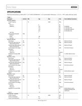
Data Sheet SPECIFICATIONS Electrical characteristics at VDD_GPO = 3.3 V, VDD_INTERFACE = 1.8 V, and all other VDDx pins = 1.3 V, TA = 25°C, unless otherwise noted. Table 1. Parameter 1 RECEIVER, GENERAL Center Frequency Gain Minimum Maximum Gain Step Received Signal Strength Indicator Range Accuracy RECEIVER, 800 MHz Noise Figure Third-Order Input Intermodulation Intercept Point Second-Order Input Intermodulation Intercept Point Local Oscillator (LO) Leakage Quadrature Gain Error Phase Error Modulation Accuracy (EVM) Input S11 RECEIVER, 2.4 GHz Noise Figure Third-Order Input Intermodulation Intercept...
Open the catalog to page 3
AD9364 Parameter 1 TRANSMITTER, 800 MHz Output S22 Maximum Output Power Modulation Accuracy (EVM) Third-Order Output Intermodulation Intercept Point Carrier Leakage Data Sheet Unit Test Conditions/Comments 1 MHz tone into 50 Ω load 19.2 MHz reference clock 0 dB attenuation 40 dB attenuation 90 MHz offset 1 MHz tone into 50 Ω load 40 MHz reference clock 0 dB attenuation 40 dB attenuation 90 MHz offset 100 Hz to 100 MHz, 30.72 MHz reference clock (doubled internally for RF synthesizer) 100 Hz to 100 MHz, 40 MHz reference clock 100 Hz to 100 MHz, 40 MHz reference clock (doubled internally for RF...
Open the catalog to page 4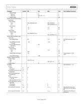
Data Sheet Parameter 1 Output Voltage Minimum Maximum Output Current DIGITAL SPECIFICATIONS (CMOS) Logic Inputs Input Voltage High Low Input Current High Low Logic Outputs Output Voltage High Low DIGITAL SPECIFICATIONS (LVDS) Logic Inputs Input Voltage Range Bus Turnaround Time, Read Test Conditions/Comments Input Differential Voltage Threshold Receiver Differential Input Impedance Logic Outputs Output Voltage High Low Output Differential Voltage Output Offset Voltage GENERAL-PURPOSE OUTPUTS Output Voltage High Low Output Current SPI TIMING SPI_CLK Period Pulse Width SPI_ENB Setup to First SPI_CLK...
Open the catalog to page 5
AD9364 Parameter 1 DIGITAL DATA TIMING (CMOS), VDD_INTERFACE = 1.8 V DATA_CLK Clock Period DATA_CLK and FB_CLK Pulse Width Tx Data Setup to FB_CLK Hold to FB_CLK DATA_CLK to Data Bus Output Delay DATA_CLK to RX_FRAME Delay Pulse Width ENABLE TXNRX TXNRX Setup to ENABLE Bus Turnaround Time Before Rx After Rx Capacitive Load Capacitive Input DIGITAL DATA TIMING (CMOS), VDD_INTERFACE = 2.5 V DATA_CLK Clock Period DATA_CLK and FB_CLK Pulse Width Tx Data Setup to FB_CLK Hold to FB_CLK DATA_CLK to Data Bus Output Delay DATA_CLK to RX_FRAME Delay Pulse Width ENABLE TXNRX TXNRX Setup to ENABLE Bus Turnaround...
Open the catalog to page 6All Analog Devices catalogs and technical brochures
 HMC722LP3E
8 Pages
 Isolated Sigma-Delta Modulator
17 Pages
 HMC853 Data Sheet
10 Pages
 AN-1084
8 Pages
 AN-1091
2 Pages
 AN_737
8 Pages
 AN-0982
4 Pages
 ADF7024
24 Pages
 AD9915
48 Pages
 AD9914
48 Pages
 ADRF6612
59 Pages
 ADRF6820
48 Pages
 ADL5246
32 Pages
 ADA4961
22 Pages
 AN-1141
8 Pages
 AN-698
36 Pages
 Temperature Sensors
2 Pages
 Reference Circuits
8 Pages
 Precision ADCs
16 Pages
 ADR02ACHIPS: ADR02ACHIPS
8 Pages
 Digital Temperature Sensors
2 Pages
 Digital to Analog Converter ICs
12 Pages
 AD1836A: Multichannel 96 kHz Codec
24 Pages


Archived catalogs
 Zero-Drift Amplifiers
2 Pages
 Powering ADI Components
8 Pages


- Ethernet switch
- Industrial network switch
- Acceleration sensor
- Unmanaged switch
- Analog Devices motor controller
- Triaxial acceleration sensor
- DC motor controller
- Data acquisition unit
- Analog Devices stepper motor controller
- Industrial converter
- Ethernet transceiver
- High-voltage amplifier
- Low-noise amplifier
- Multiplexer
- Compact motor controller
- Gyroscope
- Closed-loop motor controller
- Digital converter