
- Catalogs
- Analog Devices
- AD8322: 5 V CATV Line Driver with Coarse Step Output Power Control


- Products
- Catalogs
- News & Trends
- Exhibitions
AD8322: 5 V CATV Line Driver with Coarse Step Output Power Control

AD8322: 5 V CATV Line Driver with Coarse Step Output Power Control
The AD8322 is a cost-effective, digitally controlled variable gain amplifier designed for coaxial line driving applications, such as cable modems compliant with the MCNS-DOCSIS upstream standard. It offers an 8-bit serial word for output gain control over a 42.14 dB range, with 6.02 dB steps.
The AD8322 features a digitally controlled variable attenuator, a low-noise fixed-gain buffer, and a low-distortion high-power amplifier. It supports differential or single-ended input signals and is optimized for driving a 75 Ω load, maintaining a constant 75 Ω output impedance during power-up and power-down.
- Supply Voltage: 5 V
- Bandwidth: 180 MHz
- Gain Range: 42.14 dB
- Output Noise Level: -46 dBmV in 160 kHz bandwidth
- Harmonic Distortion: -58 dBc at 21 MHz
- Operating Temperature: -40°C to +85°C
The AD8322 is suitable for DOCSIS-compliant data modems, interactive set-top boxes, PC plug-in modems, and general-purpose digitally controlled variable gain blocks.
The device achieves low distortion with an output level up to 60 dBmV at 21 MHz bandwidth, featuring a gain linearity error of ±0.2 dB and a power-up settling time to 1 mV of 300 ns.
The AD8322 uses a serial peripheral interface (SPI) for gain programming, requiring three digital control lines: DATEN, SDATA, and CLK.
The AD8322 is available in a 28-lead TSSOP package, with an evaluation board also available.
- Supply Voltage: 6 V
- Input Voltages: ±0.5 V
- Operating Temperature Range: -40°C to +85°C
- Storage Temperature Range: -65°C to +150°C
The gain (AV) is 29.5 dB for CODE values ≥ 128. A graph illustrates gain versus gain code for an 8-bit word, excluding code 0, which provides -85 dB isolation.
Inputs VIN+ and VIN- have a DC bias level of VCC/2 and should be AC-coupled. Differential input impedance is approximately 235 Ω, and single-ended input impedance is 210 Ω. The output impedance is maintained at 75 Ω, with a 1:1 transformer recommended for impedance matching.
Proper RF design techniques include decoupling each VCC pin with capacitors and maintaining a low impedance ground plane. Layout should minimize crosstalk by keeping input and output traces short and symmetrical.
During initial power-up, the gain setting is indeterminate, and the PD pin should be held low. The asynchronous PD pin reduces power consumption by 52% when activated.
The AD8322 is characterized for DOCSIS compliance, delivering 58 dBmV output power. Harmonic distortion and adjacent channel power (ACP) are discussed with specific performance metrics.
The output noise spectral density is 12 nV/√Hz at minimum gain, meeting DOCSIS requirements. The signal-to-noise ratio improves with increased gain.
The AD8322 evaluation board allows control via a PC parallel port and includes features for gain adjustment and asynchronous PD pin control. It supports both single-ended and differential input configurations.
A 1:1 transformer is necessary for coupling differential outputs to the cable. The evaluation board includes a PULSE diplexer for low-pass filtering.
The evaluation board supports various configurations for differential input signals, with specific resistor values provided for different input impedances.
Instructions for installing and running the evaluation board control software are provided, including gain/attenuation control and power-up/power-down operations.
- Capacitors: 12 units of 0.1 µF, 50 V, 1206 size ceramic chip capacitors.
- Resistors: 10 units of 1/8 W, 1206 size chip resistors; 1 unit of 118 Ω, 1% tolerance, 1/8 W, 1206 size chip resistor.
- Test Points: 8 white test points for various signals, 1 black test point for GND, 1 red test point for VCC, and 2 yellow test points for +/- INPUT.
- Connectors: 4 right-angle BNC connectors, 1 Centronics type 36-pin right-angle female connector, 2 5-way metal binding posts.
- Transformers and Diplexers: 1 TOKO transformer, 1 PULSE diplexer with specified part numbers.
- Integrated Circuits: 1 AD8322 (TSSOP) and its evaluation PC board.
- Do not install specified capacitors, test points, resistors, and transformers as listed.
- Various screws, washers, and nuts for assembly, with specific sizes and materials detailed.
- Dimensions for the AD8322 28-Lead TSSOP package are provided in both inches and millimeters.
Catalog excerpts

REV. 0 Information furnished by Analog Devices is believed to be accurate and reliable. However, no responsibility is assumed by Analog Devices for its use, nor for any infringements of patents or other rights of third parties which may result from its use. No license is granted by implication or otherwise under any patent or patent rights of Analog Devices. a AD8322 One Technology Way, P.O. Box 9106, Norwood, MA 02062-9106, U.S.A. Tel: 781/329-4700 World Wide Web Site: http://www.analog.com Fax: 781/326-8703 © Analog Devices, Inc., 2000 5 V CATV Line Driver Coarse Step Output Power Control FUNCTIONAL BLOCK DIAGRAM DECODE SHIFT REGISTER DATA LATCH AD8322 VIN+ VIN– VOUT+ VOUT– BUFFER R1 R2 ATTENUATION CORE 8 8 8 POWER-DOWN LOGIC POWER AMP DATEN DATA CLK GND (12 PINS) PD ZIN (SINGLE) = 210 ZIN (DIFF) = 235 ZOUT DIFF = 75 VCC (7 PINS) DIFF OR SINGLE INPUT AMP FEATURES Supports DOCSIS Standard for Reverse Path Transmission Gain Programmable in 6 dB Steps Over a 42 dB Range Low Distortion at 60 dBmV Output –58 dBc SFDR at 21 MHz –56 dBc SFDR at 42 MHz Output Noise Level –46 dBmV in 160 kHz Bandwidth Maintains 75 Output Impedance Power-Up and Power-Down Condition 180 MHz Bandwidth 5 V Supply Operation Supports SPI Interfaces APPLICATIONS Gain Programmable Line Driver DOCSIS-Compliant Data Modems Interactive Set-Top Boxes PC Plug-in Modems General-Purpose Digitally Controlled Variable Gain Block GENERAL DESCRIPTION The AD8322 is a low-cost, digitally controlled variable gain amplifier optimized for coaxial line driving applications such as cable modems that are designed to the MCNS-DOCSIS upstream standard. An 8-bit serial word determines the desired output gain over a 42.14 dB range, with gain steps of 6.02 dB/major carry. The AD8322 comprises a digitally controlled variable attenuator of 0 dB to –42.14 dB, which is preceded by a low-noise, fixed-gain buffer and is followed by a low-distortion, high-power amplifier. The AD8322 accepts a differential or single-ended input signal. The output is specified for driving a 75 Ù load, such as coaxial cable. Distortion performance of –58 dBc is achieved with an output level up to 60 dBmV at 21 MHz bandwidth. A key performance and cost advantage of the AD8322 results from the ability to maintain a constant 75 Ù output impedance during power-up and powerdown conditions. This eliminates the need for external 75 Ù termination resulting in twice the effective output voltage when compared to a standard operational amplifier. The AD8322 is packaged in a low-cost 28-lead TSSOP, operates from a single 5 V supply, and has an operational temperature range of –40°C to +85°C. GAIN CODE – Decimal 1 –55 DISTORTION – dBc –60 –65 –70 –75 2 4 8 16 32 64 128 fO = 42MHz VO = 60dBmV @ MAX GAIN HD3 HD2 Figure 1. Harmonic Distortion vs. Gain Control
Open the catalog to page 1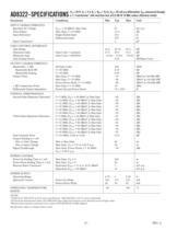
–2– REV. 0 AD8322–SPECIFICATIONS (TA = 25C, VS = 5 V, RL = RIN = 75 , VIN = 92 mV p-p differential, VOUT measured through a 1:1 transformer1 with insertion loss of 0.5 dB @ 10 MHz unless otherwise noted) Parameter Conditions Min Typ Max Unit INPUT CHARACTERISTICS Specified AC Voltage POUT = 60 dBmV, Max Gain 92 mV p-p Noise Figure Max Gain, f = 10 MHz 11.8 dB Input Resistance Single-Ended Input 210 Ù Differential Input 235 Ù Input Capacitance 2 pF GAIN CONTROL INTERFACE Gain Range 41.0 42.14 43.2 dB Maximum Gain Gain Code = 1xxxxxxx 27.5 29.5 31.5 dB Minimum Gain Gain Code = 00000001 –14.64 –12.64...
Open the catalog to page 2
REV. 0 AD8322 –3– LOGIC INPUTS (TTL/CMOS Compatible Logic) Parameter Min Typ Max Unit Logic “1” Voltage 2.1 5.0 V Logic “0” Voltage 0 0.8 V Logic “1” Current (VINH = 5 V) CLK, SDATA, DATEN 0 20 nA Logic “0” Current (VINL = 0 V) CLK, SDATA, DATEN –600 –100 nA Logic “1” Current (VINH = 5 V) PD 50 190 ìA Logic “0” Current (VINL = 0 V) PD –250 –30 ìA TIMING REQUIREMENTS Parameter Min Typ Max Unit Clock Pulsewidth (TWH) 16.0 ns Clock Period (TC) 32.0 ns Setup Time SDATA vs. Clock (TDS) 5.0 ns Setup Time DATEN vs. Clock (TES) 15.0 ns Hold Time SDATA vs. Clock (TDH) 5.0 ns Hold Time DATEN vs. Clock...
Open the catalog to page 3
REV. 0 AD8322 –4– ORDERING GUIDE Model Temperature Range Package Description JA Package Option AD8322ARU –40°C to +85°C 28-Lead TSSOP 67.7°C/W* RU-28 AD8322ARU-REEL –40°C to +85°C 28-Lead TSSOP 67.7°C/W* RU-28 AD8322-EVAL Evaluation Board *Thermal Resistance measured on SEMI standard 4-layer board. ABSOLUTE MAXIMUM RATINGS* Supply Voltage +VS Pins 6, 8, 9, 20, 21, 23, 27 . . . . . . . . . . . . . . . . . . . . . . . 6 V Input Voltages Pins 25, 26 . . . . . . . . . . . . . . . . . . . . . . . . . . . . . . . . ±0.5 V Pins 1, 2, 3, 7 . . . . . . . . . . . . . . . . . . . . . . . –0.8 V to +5.5...
Open the catalog to page 4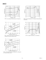
REV. 0 AD8322 –6– FREQUENCY – MHz 0 1 1k FEEDTHROUGH – dBc 10 100 –10 –20 –30 –40 –50 –60 –70 –80 –90 –100 MAX GAIN MIN GAIN GAIN CODE 0 PD = 0 TPC 6. Input Signal Feedthrough vs. Frequency FUNDAMENTAL FREQUENCY – MHz –45 5 65 DISTORTION – dBc –50 –55 –60 –65 15 25 35 45 55 PO = 58dBmV at MAX GAIN PO = 62dBmV at MAX GAIN PO = 60dBmV at MAX GAIN TPC 7. Second Order Harmonic Distortion vs. Frequency for Various Output Levels FUNDAMENTAL FREQUENCY – MHz –45 5 65 DISTORTION – dBc –50 –60 –70 –75 15 25 35 45 55 –55 –65 PO = 62dBmV at MAX GAIN PO = 58dBmV at MAX GAIN PO = 60dBmV at MAX GAIN TPC 8....
Open the catalog to page 6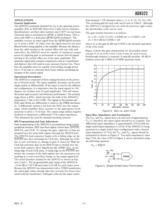
REV. 0 AD8322 –7– APPLICATIONS General Application The AD8322 is primarily intended for use as the upstream power amplifier (PA) in DOCSIS (Data Over Cable Service Interface Specifications) certified cable modems and CATV set-top boxes. Upstream data is modulated in QPSK or QAM format. This is done with DSP or a dedicated QPSK/QAM modulator. The amplifier receives its input signal from the QPSK/QAM modulator or from a DAC. In either case the signal must be low-pass filtered before being applied to the amplifier. Because the distance from the cable modem to the central office will vary with each...
Open the catalog to page 7All Analog Devices catalogs and technical brochures
 HMC722LP3E
8 Pages
 Isolated Sigma-Delta Modulator
17 Pages
 HMC853 Data Sheet
10 Pages
 AN-1084
8 Pages
 AN-1091
2 Pages
 AN_737
8 Pages
 AN-0982
4 Pages
 ADF7024
24 Pages
 AD9915
48 Pages
 AD9914
48 Pages
 ADRF6612
59 Pages
 ADRF6820
48 Pages
 ADL5246
32 Pages
 ADA4961
22 Pages
 AN-1141
8 Pages
 AN-698
36 Pages
 Temperature Sensors
2 Pages
 Reference Circuits
8 Pages
 Precision ADCs
16 Pages
 ADR02ACHIPS: ADR02ACHIPS
8 Pages
 AD9364 RF Agile Transceiver
32 Pages
 Digital Temperature Sensors
2 Pages
 Digital to Analog Converter ICs
12 Pages
 AD1836A: Multichannel 96 kHz Codec
24 Pages










































Archived catalogs
 Zero-Drift Amplifiers
2 Pages
 Powering ADI Components
8 Pages








- Ethernet switch
- Industrial network switch
- Acceleration sensor
- Unmanaged switch
- Analog Devices motor controller
- Transceiver module
- Triaxial acceleration sensor
- DC motor controller
- Data acquisition unit
- Analog Devices stepper motor controller
- Industrial converter
- Ethernet transceiver
- Processor
- High-voltage amplifier
- Low-noise amplifier
- Multiplexer
- Compact motor controller
- Digital converter
- Closed-loop motor controller
- Digital motor controller