- Catalogs
- Analog Devices
- AD809: 155 MHz Frequency Synthesizer
AD809: 155 MHz Frequency Synthesizer

AD809: 155 MHz Frequency Synthesizer
- Frequency synthesis up to 155.52 MHz.
- Input options: 19.44 MHz or 9.72 MHz.
- Single supply operation: +5 V or –5.2 V.
- Output jitter: 2.0 degrees RMS.
- Low power consumption: 90 mW.
- Compatible with 10 KH ECL/PECL outputs and 10 KH ECL/PECL/TTL/CMOS inputs.
- Package: 16-Pin Narrow 150 Mil SOIC.
- Tracking and capture range: 19.42-19.46 MHz for ×8 synthesis, 9.71-9.73 MHz for ×16 synthesis.
- Output jitter: 1.6-2.9 degrees RMS for both ×8 and ×16 synthesis.
- Input voltage levels: PECL and TTL/CMOS compatible.
- Output voltage levels: PECL logic high and low specified.
- Operating temperature range: -40°C to +85°C.
- Supply voltage: +12 V.
- Input voltage: VCC + 0.6 V.
- Maximum junction temperature: +165°C.
- Storage temperature range: -65°C to +150°C.
- ESD rating: 1500 V (Human Body Model).
- Use a single ground plane for both analog and digital grounds.
- Power supply connections should include a 10 µF capacitor between VCC and ground.
- 50 Ω transmission lines are recommended for PECL inputs.
- Termination resistors should be used for PECL input signals.
Catalog excerpts

REV. A Information furnished by Analog Devices is believed to be accurate and reliable. However, no responsibility is assumed by Analog Devices for its use, nor for any infringements of patents or other rights of third parties which may result from its use. No license is granted by implication or otherwise under any patent or patent rights of Analog Devices. a 155.52 MHz Frequency Synthesizer AD809 FEATURES Frequency Synthesis to 155.52 MHz 19.44 MHz or 9.72 MHz Input Reference Signal Select Mux Single Supply Operation: +5 V or –5.2 V Output Jitter: 2.0 Degrees RMS Low Power: 90 mW 10 KH ECL/PECL Compatible Output 10 KH ECL/PECL/TTL/CMOS Compatible Input Package: 16-Pin Narrow 150 Mil SOIC One Technology Way, P.O. Box 9106, Norwood, MA 02062-9106, U.S.A. Tel: 617/329-4700 World Wide Web Site: http://www.analog.com Fax: 617/326-8703 © Analog Devices, Inc., 1997 155.52 Mbps ports. The AD809 can be applied to create the transmit bit clock for one or more ports. An input signal multiplexer supports loop-timed applications where a 155.52 MHz transmit bit clock is recovered from the 155.52 Mbps received data. The low jitter VCO, low power and wide operating temperature range make the device suitable for generating a 155.52 MHz bit clock for SONET/SDH/Fiber in the Loop systems. The device has a low cost, on-chip VCO that locks to either 8´ or 16´ the frequency at the 19.44 MHz or 9.72 MHz input. No external components are needed for frequency synthesis; however, the user can adjust loop dynamics through selection of a damping factor capacitor whose value determines loop damping. The AD809 design guarantees that the clock output frequency will drift low (by roughly 20%) in the absence of a signal at the input. The AD809 consumes 90 mW and operates from a single power supply at either +5 V or –5.2 V. PRODUCT DESCRIPTION The AD809 provides a 155.52 MHz ECL/PECL output clock from either a 19.44 MHz or a 9.72 MHz TTL/CMOS/ECL/PECL reference frequency. The AD809 functionality supports a distributed timing architecture, allowing a backplane or PCB 19.44 MHz or 9.72 MHz timing reference signal to be distributed to multiple FUNCTIONAL BLOCK DIAGRAM AUTO SELECT PFD LOOP FILTER VCO AUTO SELECT DIVIDE BY 8/16 BW ADJUST MUX CLKOUTN (155MHz PECL OUTPUT) CLKIN TTL/CMOSIN (155MHz) MUX CF1 CF2 AD809 15 1 2 10 12 13 7 8 5 4 CLKOUT (19.44MHz OR 9.72MHz)CLKINN PECLIN PECLINN
Open the catalog to page 1
AD809–SPECIFICATIONS Parameter Condition Min Typ Max Units TRACKING AND CAPTURE RANGE1 ´8 Synthesis 19.42 19.46 MHz ´16 Synthesis 9.71 9.73 MHz OUTPUT JITTER ´8 Synthesis 1.6 2.9 Degrees RMS ´16 Synthesis 1.6 2.9 Degrees RMS JITTER TRANSFER Bandwidth 200 kHz Peaking CD = 5.6 nF (z = 5) 0.08 dB CD = 22 nF (z = 10) 0.02 dB DUTY CYCLE TOLERANCE ´8 or ´16 Synthesis Output Jitter £ 2.9 Degrees RMS 15 85 % INPUT VOLTAGE LEVELS PECL Input Logic High, VIH @ CLKIN/N and 3.8 VCC Volts Input Logic Low, VIL PECLIN/N Inputs 3.1 3.6 Volts TTL Input Logic High, VIH @ TTL/CMOSIN 2.0 Volts Input Logic Low, VIL...
Open the catalog to page 2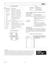
AD809 REV. A –3– Table I. MUX Input Input Selected TTL “0” CLKIN/CLKINN TTL “1” PECLIN/PECLINN Table II. Applying a PECL/ECL or CMOS/TTL Reference Input to the AD809 Input Reference AD809 Configuration PECL/ECL Differential Apply the valid PECL–level reference frequency to Pins 13 and 12. AD809 frequency synthesizer ignores the input at Pin 10. TTL/CMOS Apply the reference frequency to Single-Ended Pin 10. Connect Pins 13 and 12 to AVEE (Pins 9 and 16). The AD809 senses the common-mode signal at these pins as less than valid PECL and selects the TTL/CMOS input as active. AD809 Phase Skew The...
Open the catalog to page 3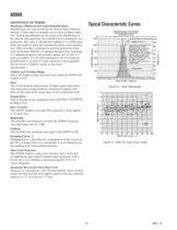
AD809 –4– REV. A DEFINITION OF TERMS Maximum, Minimum and Typical Specifications Specifications for every parameter are derived from statistical analyses of data taken on multiple devices from multiple wafer lots. Typical specifications are the mean of the distribution of the data for that parameter. If a parameter has a maximum (or a minimum), that value is calculated by adding to (or subtracting from) the mean six times the standard deviation of the distribution. This procedure is intended to tolerate production variations: if the mean shifts by 1.5 standard deviations, the remaining 4.5 standard...
Open the catalog to page 4
AD809 REV. A –5– USING THE AD809 Ground Planes Use of one ground plane for connections to both analog and digital grounds is recommended. Power Supply Connections Use of a 10 mF capacitor between VCC and ground is recommended. Care should be taken to isolate the +5 V power trace to VCC2 (Pin 3). The VCC2 pin is used inside the device to provide the CLKOUT/CLKOUTN signals. Use of a trace connecting Pin 14 and Pin 6 (AVCC2 and VCC1 respectively) is recommended. Use of 0.1 mF capacitors between IC power supply and ground is recommended. Power supply decoupling should take place as close to the IC...
Open the catalog to page 5
AD809 –6– REV. A Figure 7. Evaluation Board: Solder Side Figure 6. Evaluation Board: Component Side
Open the catalog to page 6
AD809 REV. A –7– Figure 8. Evaluation Board: INT2
Open the catalog to page 7All Analog Devices catalogs and technical brochures
 HMC722LP3E
8 Pages
 Isolated Sigma-Delta Modulator
17 Pages
 HMC853 Data Sheet
10 Pages
 AN-1084
8 Pages
 AN-1091
2 Pages
 AN_737
8 Pages
 AN-0982
4 Pages
 ADF7024
24 Pages
 AD9915
48 Pages
 AD9914
48 Pages
 ADRF6612
59 Pages
 ADRF6820
48 Pages
 ADL5246
32 Pages
 ADA4961
22 Pages
 AN-1141
8 Pages
 AN-698
36 Pages
 Temperature Sensors
2 Pages
 Reference Circuits
8 Pages
 Precision ADCs
16 Pages
 ADR02ACHIPS: ADR02ACHIPS
8 Pages
 AD9364 RF Agile Transceiver
32 Pages
 Digital Temperature Sensors
2 Pages
 Digital to Analog Converter ICs
12 Pages
 AD1836A: Multichannel 96 kHz Codec
24 Pages


Archived catalogs
 Zero-Drift Amplifiers
2 Pages
 Powering ADI Components
8 Pages


- Ethernet switch
- Industrial network switch
- Acceleration sensor
- Unmanaged switch
- Transceiver module
- Analog Devices motor controller
- Triaxial acceleration sensor
- DC motor controller
- Data acquisition unit
- Analog Devices stepper motor controller
- Industrial converter
- Ethernet transceiver
- Processor
- High-voltage amplifier
- Low-noise amplifier
- Compact motor controller
- Gyroscope
- Closed-loop motor controller
- Digital converter