
- Catalogs
- Analog Devices
- AD5623R/AD5643R/AD5663R: Dual 12-/14-/16-Bit nanoDAC® with 5 ppm/°C On-Chip


- Products
- Catalogs
- News & Trends
- Exhibitions
AD5623R/AD5643R/AD5663R: Dual 12-/14-/16-Bit nanoDAC® with 5 ppm/°C On-Chip

AD5623R/AD5643R/AD5663R: Dual 12-/14-/16-Bit nanoDAC® with 5 ppm/°C On-Chip
- Available in 12-, 14-, and 16-bit resolutions.
- On-chip 1.25 V/2.5 V reference with 5 ppm/°C stability.
- Low power consumption: 0.6 mW at 3 V and 1.25 mW at 5 V.
- Power-on reset to zero scale and per channel power-down.
- Serial interface up to 50 MHz compatible with SPI®, QSPI™, MICROWIRE™, and DSP standards.
- Static performance includes relative accuracy and differential nonlinearity, guaranteed monotonic by design.
- Output voltage range from 0 to VDD with capacitive load stability.
- Reference inputs and outputs with specific current and voltage ranges.
- Logic inputs with defined voltage levels and current specifications.
- Power requirements vary with internal reference on or off.
- Power-On Reset: Controls output voltage during power-up, output powers up to 0 V until a valid write sequence is made.
- Software Reset: Contains two reset modes, programmable by setting a control register bit.
- Power-Down Modes: Four modes available, reducing power consumption and switching output stage to a resistor network.
- Internal Reference: On-chip reference is off at power-up, enabled via a control register. Recommended to use a 100 nF capacitor for stability.
- External Reference: Allows use of an external reference if required, with default condition being the on-chip reference off at power-up.
- Serial Interface: 3-wire interface compatible with SPI, QSPI, and MICROWIRE standards, supporting high-speed DSPs.
- Gain Temperature Coefficient: Change in gain error with temperature changes, expressed in ppm/°C.
- Zero-Scale Error Drift: Change in zero-scale error with temperature, expressed in µV/°C.
- DC Crosstalk: DC change in output level of one DAC in response to another DAC's output change, expressed in µV.
- Multiplying Bandwidth: Frequency at which output amplitude falls to 3 dB below input.
Catalog excerpts

Dual 12-/14-/16-Bit nanoDAC® with 5 ppm/°C On-Chip Reference AD5623R/AD5643R/AD5663R Data Sheet FEATURES FUNCTIONAL BLOCK DIAGRAM VREFIN /VREFOUT 1.25V/2.5V REFERENCE LDAC INPUT REGISTER INPUT REGISTER INTERFACE LOGIC POWER-DOWN LOGIC Low power, smallest pin-compatible, dual nanoDAC AD5663R: 16 bits AD5643R: 14 bits AD5623R: 12 bits User-selectable external or internal reference External reference default On-chip 1.25 V/2.5 V, 5 ppm/°C reference 10-lead MSOP and 3 mm × 3 mm LFCSP 2.7 V to 5.5 V power supply Guaranteed monotonic by design Power-on reset to zero scale Per channel power-down Serial interface up to 50 MHz Hardware LDAC and CLR functions Table 1. Related Devices Part No. AD5663 Description 2.7 V to 5.5 V, dual 16-bit nanoDAC, with external reference Process control Data acquisition systems Portable battery-powered instruments Digital gain and offset adjustment Programmable voltage and current sources Programmable attenuators GENERAL DESCRIPTION The AD5623R/AD5643R/AD5663R, members of the nanoDAC family, are low power, dual 12-, 14-, and 16-bit buffered voltageout digital-to-analog converters (DAC) that operate from a single 2.7 V to 5.5 V supply and are guaranteed monotonic by design. The AD5623R/AD5643R/AD5663R have an on-chip reference. The AD5623R-3/AD5643R-3/AD5663R-3 have a 1.25 V, 5 ppm/°C reference, giving a full-scale output of 2.5 V; and the AD5623R-5/ AD5643R-5/AD5663R-5 have a 2.5 V, 5 ppm/°C reference, giving a full-scale output of 5 V. The on-chip reference is off at power-up, allowing the use of an external reference; and all devices can be operated from a single 2.7 V to 5.5 V supply. The internal reference is turned on by writing to the DAC. The parts incorporate a power-on reset circuit that ensures the DAC output powers up to 0 V and remains there until a valid write takes place. The part contains a power-down feature that reduces the current consumption of the device to 480 nA at 5 V and provides software-selectable output loads while in powerdown mode. The low power consumption of this part in normal operation makes it ideally suited to portable, battery-operated equipment. The AD5623R/AD5643R/AD5663R use a versatile, 3-wire serial interface that operates at clock rates up to 50 MHz, and they are compatible with standard SPI®, QSPI™, MICROWIRE™, and DSP interface standards. The on-chip precision output amplifier enables rail-to-rail output swing to be achieved. PRODUCT HIGHLIGHTS 1. Dual 12-, 14-, and 16-bit DAC. 2. On-chip 1.25 V/2.5 V, 5 ppm/°C reference. 3. Available in 10-lead MSOP and 10-lead, 3 mm × 3 mm LFCSP. 4. Low power; typically consumes 0.6 mW at 3 V and 1.25 mW at 5 V. 5. 4.5 μs maximum settling time for the AD5623R. Document Feedback Information furnished by Analog Devices is believed to be accurate and reliable. However, no responsibility is assumed by Analog Devices for its use, nor for any infringements of patents or other rights of third parties that may result from its use. Specifications subject to change without notice. No license is granted by implication or otherwise under any patent or patent rights of Analog Devices. Trademarks and registered trademarks are the property of their respective owners. One Technology Way, P.O. Box 9106, Norwood, MA 02062-9106, U.S.A. Tel: 781.329.4700 ©2006–2013 Analog Devices, Inc. All rights reserved. Technical Support www.analog.com
Open the catalog to page 1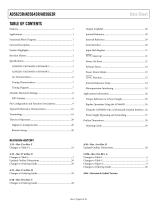
Data Sheet Using the AD5663R with a Galvanically Isolated Interface . 26
Open the catalog to page 2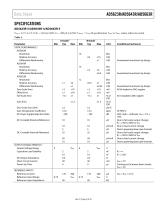
Data Sheet SPECIFICATIONS AD5623R-5/AD5643R-5/AD5663R-5 VDD = 4.5 V to 5.5 V; RL = 2 kΩ to GND; CL = 200 pF to GND; VREFIN = VDD; all specifications TMIN to TMAX, unless otherwise noted. Table 2. Parameter STATIC PERFORMANCE 2 AD5663R Resolution Relative Accuracy Differential Nonlinearity AD5643R Resolution Relative Accuracy Differential Nonlinearity AD5623R Resolution Relative Accuracy Differential Nonlinearity Zero-Scale Error Offset Error Full-Scale Error Guaranteed monotonic by design Guaranteed monotonic by design Zero-Scale Error Drift Gain Temperature Coefficient DC Power Supply Rejection...
Open the catalog to page 3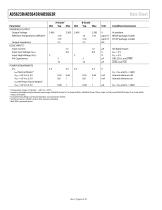
AD5623R/AD5643R/AD5663R Parameter REFERENCE OUTPUT Output Voltage Reference Temperature Coefficient3 Output Impedance LOGIC INPUTS3 Input Current Input Low Voltage (VINL) Input High Voltage (VINH) Pin Capacitance POWER REQUIREMENTS VDD IDD (Normal Mode) 4 VDD = 4.5 V to 5.5 V VDD = 4.5 V to 5.5 V IDD (All Power-Down Modes) 5 VDD = 4.5 V to 5.5 V Data Sheet At ambient MSOP package models LFCSP package models All digital inputs VDD = 5 V VDD = 5 V DIN, SCLK, and SYNC LDAC and CLR VIH = VDD and VIL = GND Internal reference off Internal reference on Temperature range: A, B grade = −40°C to +105°C....
Open the catalog to page 4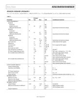
Data Sheet AD5623R-3/AD5643R-3/AD5663R-3 VDD = 2.7 V to 3.6 V; RL = 2 kΩ to GND; CL = 200 pF to GND; VREFIN = VDD; all specifications TMIN to TMAX, unless otherwise noted. Table 3. Parameter STATIC PERFORMANCE 2 AD5663R Resolution Relative Accuracy Differential Nonlinearity AD5643R Resolution Relative Accuracy Differential Nonlinearity AD5623R Resolution Relative Accuracy Differential Nonlinearity Zero-Scale Error Offset Error Full-Scale Error Gain Error Zero-Scale Error Drift Gain Temperature Coefficient DC Power Supply Rejection Ratio DC Crosstalk (External Reference) Guaranteed monotonic by...
Open the catalog to page 5
AD5623R/AD5643R/AD5663R Parameter LOGIC INPUTS3 Input Current VINL, Input Low Voltage VINH, Input High Voltage Pin Capacitance Data Sheet B Grade 1 Typ Max All digital inputs VDD = 3 V VDD = 3 V DIN, SCLK, and SYNC LDAC and CLR VIH = VDD and VIL = GND Internal reference off Internal reference on POWER REQUIREMENTS VDD IDD (Normal Mode) 4 VDD = 2.7 V to 3.6 V VDD = 2.7 V to 3.6 V IDD (All Power-Down Modes) 5 VDD = 2.7 V to 3.6 V Temperature range: B grade = −40°C to +105°C. Linearity calculated using a reduced code range: AD5663R (Code 512 to Code 65,024), AD5643R (Code 128 to Code 16,256), and...
Open the catalog to page 6
Data Sheet TIMING CHARACTERISTICS All input signals are specified with tR = tF = 1 ns/V (10% to 90% of VDD) and timed from a voltage level of (VIL + VIH)/2. VDD = 2.7 V to 5.5 V; all specifications TMIN to TMAX, unless otherwise noted.1 Table 5. Limit at TMIN, TMAX VDD = 2.7 V to 5.5 V SCLK cycle time SCLK high time SCLK low time SYNC to SCLK falling edge setup time Data setup time Data hold time SCLK falling edge to SYNC rising edge Minimum SYNC high time SYNC rising edge to SCLK fall ignore SCLK falling edge to SYNC fall ignore LDAC pulse width low SCLK falling edge to LDAC rising edge SCLK...
Open the catalog to page 7All Analog Devices catalogs and technical brochures
 HMC722LP3E
8 Pages
 Isolated Sigma-Delta Modulator
17 Pages
 HMC853 Data Sheet
10 Pages
 AN-1084
8 Pages
 AN-1091
2 Pages
 AN_737
8 Pages
 AN-0982
4 Pages
 ADF7024
24 Pages
 AD9915
48 Pages
 AD9914
48 Pages
 ADRF6612
59 Pages
 ADRF6820
48 Pages
 ADL5246
32 Pages
 ADA4961
22 Pages
 AN-1141
8 Pages
 AN-698
36 Pages
 Temperature Sensors
2 Pages
 Reference Circuits
8 Pages
 Precision ADCs
16 Pages
 ADR02ACHIPS: ADR02ACHIPS
8 Pages
 AD9364 RF Agile Transceiver
32 Pages
 Digital Temperature Sensors
2 Pages
 Digital to Analog Converter ICs
12 Pages
 AD1836A: Multichannel 96 kHz Codec
24 Pages











































Archived catalogs
 Zero-Drift Amplifiers
2 Pages
 Powering ADI Components
8 Pages








- Ethernet switch
- Industrial network switch
- Acceleration sensor
- Unmanaged switch
- Analog Devices motor controller
- Transceiver module
- Triaxial acceleration sensor
- DC motor controller
- Analog Devices stepper motor controller
- Industrial converter
- Ethernet transceiver
- Processor
- High-voltage amplifier
- Low-noise amplifier
- Multiplexer
- Compact motor controller
- Digital converter
- Closed-loop motor controller
- Digital motor controller