
- Catalogs
- Analog Devices
- AD1990: Class-D Audio Power Amplifier – 2 × 5W


- Products
- Catalogs
- News & Trends
- Exhibitions
AD1990: Class-D Audio Power Amplifier – 2 × 5W

AD1990: Class-D Audio Power Amplifier – 2 × 5W
The AD1990 is an integrated stereo modulator and power stage amplifier with features including less than 0.002% THD + N, a 101 dB dynamic range, and 2 × 5 W output power at 4 Ω with less than 0.01% THD + N. It offers short-circuit and overtemperature protection, an EMI optimized modulator, and pop noise suppression.
This amplifier is ideal for advanced televisions, compact multimedia systems, and minicomponents.
The AD1990 is a 2-channel, bridge-tied load (BTL), switching audio power amplifier with an integrated Σ-Δ modulator. It operates over a power supply voltage range of 8 V to 12 V, with the modulator and digital logic operating from a 5 V supply.
Key specifications include supply voltages of AVDD and DVDD at 5 V, PVDD at 12 V, and a load impedance of 6 Ω. The amplifier has a thermal warning active at 135°C and thermal shutdown active at 150°C.
The document provides a detailed pin configuration and function descriptions for the AD1990, including power supply pins, output pins, and control pins.
Graphs illustrate performance characteristics such as output power into various loads, THD vs. frequency, and maximum output power vs. PVDD voltage.
The AD1990 operates as a high-performance, switching audio power amplifier with a Σ-Δ modulator that converts analog input signals to a switching waveform for direct speaker drive.
The document describes the AD1990, a Class-D audio power amplifier utilizing Σ-Δ modulation for efficient and linear amplification of audio frequencies. It includes features such as overcurrent and over-temperature protection, and silent transitions during power on/off.
The AD1990 employs Σ-Δ modulation instead of pulse-width modulation (PWM), offering benefits like reduced harmonic distortion in the AM frequency band and excellent linearity. Feedback from the power stage compensates for nonlinearities and reduces sensitivity to power supply variations. The modulator operates at a sampling frequency of approximately 6 MHz, ensuring no aliasing issues within the audio band.
The AD1990 features a low power consumption mode when the RESET pin is asserted. Upon deassertion, a start-up sequence initializes the modulator and protection circuits. The MUTE function allows for a soft-start sequence to prevent audible noise.
Proper power-up sequencing is crucial to avoid latch-up issues. The AD1990 should be powered with RESET and MUTE held low until power supplies stabilize. A soft unmute sequence should follow to prevent audible pops.
The amplifier has single-ended inputs and uses an internal amplifier to bias the input signal. The modulator gain is set using feedback from the power output stage, requiring a voltage divider to scale feedback appropriately. Recommended resistor values are provided for different supply voltages.
The AD1990 includes a PGA to boost overall gain, selectable via PGA1 and PGA0 pins, offering four gain settings.
The output stage features a full H-bridge configuration with integrated MOSFETs. The power supply should be between 8 V and 20 V. Nonoverlap time settings are adjustable to balance distortion and efficiency.
The modulator requires an external clock source, typically 12.288 MHz, with a tolerance of ±10%. The clock affects the noise floor and efficiency of the amplifier.
The AD1990 includes thermal and overcurrent protection. Thermal protection triggers at 135°C and shuts down at 150°C. Overcurrent protection mutes the amplifier if current exceeds 4 A, requiring manual reset.
Example application circuits are provided, illustrating connections for power, feedback, and error reporting.
The document provides a schematic for a typical application circuit involving the AD1990, highlighting various components such as capacitors (4.7µF, 0.1µF, 47µF, 10µF, 1000µF), resistors (R1 = 4.2kΩ, R2 = 1.8kΩ), an inductor (L = 18µH), and a load (6Ω). Key connections include digital inputs, power supply pins (PVDD, AVDD, DVDD), and ground connections (AGND, DGND, PGND).
The document specifies the dimensions of the AD1990 package, compliant with JEDEC standards MO-220-VMMD-4. The package is a 64-Lead Lead Frame Chip Scale Package (LFCSP_VQ) with dimensions of 9 mm × 9 mm. Detailed measurements are provided for various aspects of the package, including pin indicators and seating plane.
The document lists different models of the AD1990 available for order, including AD1990ACPZ1, AD1990ACPZRL1, and AD1990ACPZRL71, all suitable for a temperature range of −40°C to +85°C. The package description is consistent across models, with variations in tape and reel options.
The document is ©2006 by Analog Devices, Inc., and notes that trademarks and registered trademarks are the property of their respective owners.
Catalog excerpts

Audio Switching Amplifier AD1990 Rev. 0 Information furnished by Analog Devices is believed to be accurate and reliable. However, no responsibility is assumed by Analog Devices for its use, nor for any infringements of patents or other rights of third parties that may result from its use. Specifications subject to change without notice. No license is granted by implication or otherwise under any patent or patent rights of Analog Devices. Trademarks and registered trademarks are the property of their respective owners. One Technology Way, P.O. Box 9106, Norwood, MA 02062-9106, U.S.A. Tel: 781.329.4700 www.analog.com Fax: 781.461.3113 ©2006 Analog Devices, Inc. All rights reserved. FEATURES Integrated stereo modulator and power stage <0.002% THD + N 101 dB dynamic range (A-weighted) 2 × 5 W output power (4 Ù, <0.01% THD + N) RDS-ON < 0.3 Ù (per transistor) PSRR > 65 dB On-off-mute pop noise suppression EMI optimized modulator Short-circuit protection Overtemperature protection Low cost DMOS process APPLICATIONS Advanced televisions Compact multimedia systems Minicomponents GENERAL DESCRIPTION The AD1990 is a 2-channel, bridge tied load (BTL), switching audio power amplifier with integrated Ó-Ä modulator. The modulator accepts a single-ended, analog input signal and converts it to a switching waveform to drive speakers directly. A digital, microprocessor-compatible interface provides control of reset, mute, and PGA gain, as well as feedback signals for thermal and overcurrent error conditions. The output stage can operate over a power supply voltages range of 8 V to 12 V. The analog modulator and digital logic operate from a 5 V supply. FUNCTIONAL BLOCK DIAGRAM B2B1A2A1OUTL+LEVELSHIFTERANDDEAD TIMECONTROLH-BRIDGEPGNDOUTL–OUTR+DCTRL2DCTRL1DCTRL0OUTR–D2D1C2C1NFR+NFR–NFL+NFL–MUTERESETERR2ERR1ERR0Ó-ÄMODULATORÓ-ÄMODULATORPGAPGAOSCILLATORVOLTAGEREFERENCEMODE CONTROLLOGIC ANDPOP/CLICKSUPPRESSIONAGNDCLKICLKOREF_FILTAINRAINLPVDDAVDDDVDDPGA1PGA0FEEDBACKNETWORKFEEDBACKNETWORKAD199005380-001 Figure 1.
Open the catalog to page 1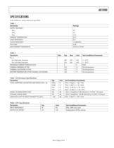
AD1990 Rev. 0 | Page 3 of 16 SPECIFICATIONS Test conditions, unless otherwise specified. Table 1. Parameter Ratings SUPPLY VOLTAGES AVDD 5 V DVDD 5 V PVDD 12 V AMBIENT TEMPERATURE 25°C LOAD IMPEDANCE 6 Ù CLOCK FREQUENCY 12.288 MHz PGA GAIN 0 dB MEASUREMENT BANDWIDTH 20 Hz to 20 kHz Table 2. Parameter Min Typ Max Unit Test Conditions/Comments RDS-ON Per High-Side Transistor 260 355 mÙ T = 25°C Per Low-Side Transistor 210 265 mÙ T = 25°C MAXIMUM CURRENT THROUGH OUTx 5 A Peak THERMAL WARNING ACTIVE 135 °C Die temperature THERMAL SHUTDOWN ACTIVE 150 °C Die temperature RESTORE TEMPERATURE AFTER THERMAL...
Open the catalog to page 3
AD1990 Rev. 0 | Page 4 of 16 Table 5. Power Supplies Parameter Min Typ Max Unit Test Conditions/Comments ANALOG SUPPLY, AVDD 4.5 5.0 5.5 V DIGITAL SUPPLY, DVDD 4.5 5.0 5.5 V POWER TRANSISTOR SUPPLY, PVDD 6.5 8 to 12 15 V RESET/POWER-DOWN CURRENT RESET held low AVDD 0.6 1 ìA 5 V DVDD 7.5 11 ìA 5 V PVDD 19 40 ìA 12 V QUIESCENT CURRENT Inputs grounded, nonoverlap = minimum AVDD 20 mA 5 V DVDD 5.5 mA 5 V PVDD 30 mA 12 V OPERATING CURRENT VIN = 1 V rms, RL = 6 Ù, PO = 1 W AVDD 20 27 mA 5 V DVDD 5.5 7 mA 5 V PVDD 218 260 mA 12 V Table 6. Digital I/O Parameter Min Typ Max Unit Test Conditions/Comments...
Open the catalog to page 4
AD1990 Rev. 0 | Page 5 of 16 ABSOLUTE MAXIMUM RATINGS Table 8. Parameter Rating AVDD, DVDD to AGND, DGND -0.3 V to +6.5 V PVDDx to PGNDx1 -0.3 V to +22.5 V AGND to DGND to PGNDx -0.3 V to +0.3 V AVDD, to DVDD -0.5 V to +0.5 V Operating Temperature Range –40°C to +85°C Storage Temperature Range –65°C to +150°C Maximum Junction Temperature 150°C Thermal Resistance èJA 19.2°C/W èJC (at the Exposed Pad Surface) 0.9°C/W èJB (on JEDEC Standard PCB) 9.7°C/W 1 Including any induced voltage due to inductive load. Stresses above those listed under Absolute Maximum Ratings may cause permanent damage to...
Open the catalog to page 5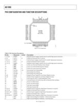
AD1990 Rev. 0 | Page 6 of 16 PIN CONFIGURATION AND FUNCTION DESCRIPTIONS PIN 1INDICATOR17181920212223242526272829303132ERR2ERR1ERR0DCTRL2DCTRL1DCTRL0DGNDDVDDDVDDDGNDCLKICLKOMUTERESETPGA1PGA06463626160595875655545352515049PGND1NFL+NFL–NCAINLNCMOD_FILTAVDDAGNDREF_FILTNCAINRNCNFR–NFR+PGND212345678910111213141516PGND1PGND1PGND1OUTL+OUTL+OUTL+PVDD1PVDD1PVDD1PVDD1OUTL–OUTL–OUTL–PGND1PGND1PGND1NC = NO CONNECTPGND2PGND2PGND2OUTR+OUTR+OUTR+PVDD2PVDD2PVDD2PVDD2OUTR–OUTR–OUTR–PGND2PGND2PGND248474645444342414039383736353433AD1990TOP VIEW(Not to Scale)05380-003 Figure 3. Pin Configuration Table 9. Pin Function...
Open the catalog to page 6
AD1990 Rev. 0 | Page 7 of 16 Pin No. Mnemonic In/Out Description 52, 54, 59, 61 NC No Connection—Should Be Left Floating. 53 AINR I Analog Input for Right Channel. 55 REF_FILT O Filter Pin for Band Gap Reference—Should Be Bypassed to AGND. 56 AGND Negative Power Supply for Low Power Analog Circuitry. 57 AVDD Positive Power Supply for Low Power Analog Circuitry. 58 MOD_FILT O Modulator Filter Pin—Used to Set Time Constant of Modulator Order Reduction Circuit. 60 AINL O Analog Input for Left Channel. 62 NFL- I Left Channel Negative Feedback—Inverting Input. 63 NFL+ I Left Channel Negative Feedback—Noninverting...
Open the catalog to page 7
AD1990 Rev. 0 | Page 8 of 16 FREQUENCY (kHz) POWER (dBFS: 0dB = Power at Which THD = 1% (5.9W)) TYPICAL PERFORMANCE CHARACTERISTICS 0–16002 0 Figure 4. 1 W Output Power into 4 Ù Load 0–16002 0 Figure 5. 1 W Output Power into 6 Ù Load 0–16002 0 Figure 6. 1 W Output Power into 8 Ù Load Figure 7. -60 dBFS Output Power into 4 Ù Load Figure 8. -60 dBFS Output Power into 6 Ù Load Figure 9. -60 dBFS Output Power into 8 Ù Load
Open the catalog to page 8
AD1990 Rev. 0 | Page 9 of 16 20–140FREQUENCY (Hz)POWER (dB, Relative to 500mW Output Power)0–20–40–60–80–100–1201001k10k05380-010 Figure 10. IMD for 19 kHz/20 kHz Twin-Tone Stimulus with 500 mW Power in Each Tone 400FREQUENCY (Hz)AMPLIFIER GAIN (dB)1001k10k3530252015105PGA GAIN = 18dBPGA GAIN = 12dBPGA GAIN = 6dBPGA GAIN = 0dB05380-011 Figure 11. Amplifier Gain vs. Frequency, 6 Ù Load, PVDD = 12 V 0–120FREQUENCY (Hz)SIGNAL IN IDLE CHANNEL (dB, Relative toDriven Channel Signal)1001k10k–20–40–60–80–100L CHANNEL DRIVEN,R CHANNEL IDLEL CHANNEL IDLE,R CHANNEL DRIVEN05380-012 Figure 12. Channel Separation...
Open the catalog to page 9All Analog Devices catalogs and technical brochures
 HMC722LP3E
8 Pages
 Isolated Sigma-Delta Modulator
17 Pages
 HMC853 Data Sheet
10 Pages
 AN-1084
8 Pages
 AN-1091
2 Pages
 AN_737
8 Pages
 AN-0982
4 Pages
 ADF7024
24 Pages
 AD9915
48 Pages
 AD9914
48 Pages
 ADRF6612
59 Pages
 ADRF6820
48 Pages
 ADL5246
32 Pages
 ADA4961
22 Pages
 AN-1141
8 Pages
 AN-698
36 Pages
 Temperature Sensors
2 Pages
 Reference Circuits
8 Pages
 Precision ADCs
16 Pages
 ADR02ACHIPS: ADR02ACHIPS
8 Pages
 AD9364 RF Agile Transceiver
32 Pages
 Digital Temperature Sensors
2 Pages
 Digital to Analog Converter ICs
12 Pages
 AD1836A: Multichannel 96 kHz Codec
24 Pages













































Archived catalogs
 Zero-Drift Amplifiers
2 Pages
 Powering ADI Components
8 Pages








- Ethernet switch
- Industrial network switch
- Acceleration sensor
- Unmanaged switch
- Analog Devices motor controller
- Transceiver module
- Triaxial acceleration sensor
- DC motor controller
- Data acquisition unit
- Analog Devices stepper motor controller
- Industrial converter
- Ethernet transceiver
- Processor
- High-voltage amplifier
- Low-noise amplifier
- Multiplexer
- Compact motor controller
- Digital converter
- Closed-loop motor controller
- Digital motor controller