NanEye / NanEye Stereo
1 /33Pages

NanEye / NanEye Stereo
1 /33Pages
Catalog excerpts

NanEye / NanEye Stereo Miniature Camera Module
Open the catalog to page 1
Document Feedback NanEye / NanEye Stereo Content Guide 9.1 Recommended LVDS Receiver 10 Package Drawings & Markings... 26
Open the catalog to page 2
Document Feedback NanEye / NanEye Stereo General Description 1 General Description NanEye is a miniature sized image sensor vision applications where size is a critical factor. The ability of the camera head to drive a signal through long cables makes this the ideal component for minimal diameter endoscopes. With a footprint of a just 1 mmx1 mm, it features a 249x250 resolution with a high sensitive 3-micron rolling shutter pixel, with large full well capacitance. The sensor has been specially designed for medical endoscopic applications where high SNR is mandatory. The sensor has a high frame...
Open the catalog to page 3
Document Feedback NanEye / NanEye Stereo General Description • Wearable Devices • Eye tracking • Virtual / Augmented reality • Gesture recognition 1.2 Applications • Medical Applications • Intraoral Scanning • Industrial Applications • Industrial endoscopy 1.3 Block Diagram The functional blocks of this device are shown below: Figure 2: Functional Blocks of NanEye / NanEye Stereo State machine Serial interface
Open the catalog to page 4
Document Feedback NanEye / NanEye Stereo Ordering Information 2 Ordering Information Ordering Code Package Optics Delivery Form CHIP only version NE2D_CHIP_B&W_SGA SGA No lens Gel-Pack B&W version NE2D_B&W_V90F2.7_2m Cabled module FOV90°; F2.7 Spool NE2D_B&W_V120F2.8_2m Cabled module FOV120°; F2.8 Spool NE2D_B&W_V160F2.4_2m Cabled module FOV160°; F2.4 Spool NE2D_B&W_V90F2.7_SGA Module only FOV90°; F2.7 Gel-Pack NE2D_B&W_V120F2.8_SGA Module only FOV120°; F2.8 Gel-Pack RGB version NE2D_RGB_V90F2.7_2m Cabled module FOV90°; F2.7 Spool NE2D_RGB_V90F4.0_2m Cabled module FOV90°; F4.0 Spool NE2D_RGB_V90F6.0_2m...
Open the catalog to page 5
Document Feedback NanEye / NanEye Stereo Pin Assignment 3 Pin Assignment 3.1 Pin Diagram Figure 3: Pin Assignment SGA (top view)
Open the catalog to page 6
Document Feedback NanEye / NanEye Stereo Pin Assignment LED - (optional) VSS Data + SDA Data -SCL VDDD LED + (optiona l) Pin Description Figure 7: Pin Description of NanEye / NanEye Stereo A2 2 3 SDA / DATA+ DIO Serial data input, LVDS pos. output B2 3 4 SCL / DATA- DIO Serial clock input, LVDS neg. output A1 4 5 VDDD Supply Positive supply (1) Explanation of abbreviations: DIO Digital Input/Output
Open the catalog to page 7
Document Feedback NanEye / NanEye Stereo Absolute Maximum Ratings 4 Absolute Maximum Ratings Stresses beyond those listed under “Absolute Maximum Ratings" may cause permanent damage to the device. These are stress ratings only. Functional operation of the device at these or any other conditions beyond those indicated under “Operating Conditions” is not implied. Exposure to absolute maximum rating conditions for extended periods may affect device reliability. Figure 8: Absolute Maximum Ratings of NanEye / NanEye Stereo Symbol Parameter Min Max Unit Comments Electrical Parameters VVDDD Supply Voltage...
Open the catalog to page 8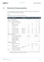
Document Feedback NanEye / NanEye Stereo Electrical Characteristics Electrical Characteristics All limits are guaranteed. The parameters with Min and Max values are guaranteed with production tests or SQC (Statistical Quality Control) methods. Figure 9: Electrical Characteristics of NanEye / NanEye Stereo Typ Supply Voltage Peak to peak noise on VDDD Internal pixel clock (adjustable via VDDD) Bit clock for serial data transmission (12x Pclk) Jitter data clock Total power consumption Total power consumption Total power consumption Total power consumption Total power consumption Digital Upstream...
Open the catalog to page 9
Document Feedback NanEye / NanEye Stereo Electrical Characteristics Remark Resolution Pixel size Optical format Pixel type Shutter type Color filters Micro lenses 62kP, 249 (H) x 250(V) 3pm x 3pm 1/16" 3T FSI Rolling Shutter RGB (Bayer Pattern) or B&W no exposure time, dark level and analog gain analog Register configurable Column ADC Adjustable over power supply @50Hz Programmable register Programmable gain Exposure times Number of defect pixel(1) Defect pixel cluster(2) ADC Frame rate Output interface Size Sensor parameter (1) A pixel is considered a defect pixel if in dark or at any homogeneous...
Open the catalog to page 10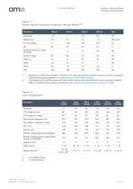
Document Feedback NanEye / NanEye Stereo Electrical Characteristics Figure 11: Electro-Optical Parameter of NanEye / NanEye Stereo(1)(2) Parameter Full well capacity 17 Temporal read noise in dark / dark noise 1 2 (1) Measured on a B&W sensor at 625nm illumination The values are all without software correction and were all measured using the following test equipment: http://www.aphesa.com/EMVA1288_setup.php. (2) The settings used to get these values are those recommended by the European Machine Vision Association standard 1288 for the Machine Vision Sensors and Cameras: http://www.emva.org/standards-technology/emva-1288/....
Open the catalog to page 11
Document Feedback NanEye / NanEye Stereo Typical Operating Characteristics 6 Typical Operating Characteristics Figure 13: B&W Spectral Response (1) Min/max values based on current available test results, limits may be adjusted when additional test data are available. (2) The frame rate is dependent on VDD sensor supply voltage. For as long as the frame rate is maintained >38 Fps the sensor supply can be set lower than 1.8V down to 1.6V minimum.
Open the catalog to page 12
Document Feedback NanEye / NanEye Stereo Typical Operating Characteristics Figure 17: NanEye CTF Measurements
Open the catalog to page 13
Document Feedback Functional Description NanEye / NanEye Stereo Functional Description Sensor Architecture Figure 2 shows the image sensor architecture. The internal state machine generates the necessary signals for image acquisition. The image is stored in the pixels (rolling shutter) and is read out sequentially, row-by-row. On the pixel output, an analog gain is possible. The pixel values then passes to a column ADC cell, in which ADC conversion is performed. The digital signals are then read out over a LVDS channel. Pixel Array The pixel array consists of 249 x 250 square rolling shutter...
Open the catalog to page 14All AMS catalogs and technical brochures
 TDC-GP21
91 Pages
 CMV50000
138 Pages
 CMV20000
48 Pages
 BELICE-850
22 Pages
 CMOSIS company brochure
3 Pages
 CHR70M
2 Pages
 CMV20000
2 Pages
 CMV12000
2 Pages
 CMV4000
2 Pages
 CMV2000
2 Pages


- Temperature probe
- Resistance temperature sensor
- Proximity switch
- Signal amplifying integrated circuit
- Position transducer
- Thermocouple temperature transducer
- Inductive proximity sensor
- Linear position transmitter
- Analog position transducer
- No-contact position sensor
- Compact temperature probe
- Magnetic position sensor
- Industrial converter
- High-temperature temperature sensor
- Industrial position sensor
- Digital temperature sensor
- Metal position sensor
- Potentiometer position sensor
- Voltage amplifier
- Absolute position sensor