BELICE-850
1 /22Pages

BELICE-850
1 /22Pages
Catalog excerpts

Abstract The BELICE infrared illuminator is the most compact dot-projector for stereoscopic imaging available today. It produces a very high-contrast dot pattern that stereo-matching algorithms can use to mitigate the problem of lack of texture, and to produce high-accuracy depth maps. BELICE enables active stereoscopic imaging to be implemented on a variety of platforms, from robotics to mobile devices.
Open the catalog to page 1
Document Feedback 8.1 PCB Pad Layout and Solder Mask 10 Soldering & Storage Information 18
Open the catalog to page 2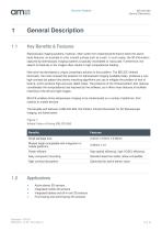
Document Feedback 1 General Description 1.1 Key Benefits & Features Stereoscopic imaging systems, however, often suffer from impaired performance when the scene lacks features: an example is a flat, smooth surface such as a wall. In such cases, the 3D information captured by stereoscopic imaging systems is typically incomplete or inaccurate. Furthermore, the search for features in the images often results in high computational loading. Now ams has developed a unique, proprietary solution to this problem. The BELICE infrared illuminator, the most compact dot-projector for stereoscopic imaging...
Open the catalog to page 3
Document Feedback Block Diagram The functional blocks of this device are shown below: Figure 2 : Functional Blocks of BELICE-850
Open the catalog to page 4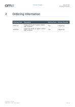
Document Feedback 2 Ordering Information Ordering Code Description Delivery Form Delivery Quantity Emitter type A with 5° pattern rotation / APDE-00 Tray 143 pcs/tray Emitter type B with 15° pattern rotation / SMT contacted
Open the catalog to page 5
Document Feedback 3 Pin Assignment 3.1 Pin Diagram Figure 3: Module Bottom View 3.2 Pin Description Figure 4: Pin Description of BELICE-850 Pin Number Pin Name Description 1 Anode VCSEL Power 2 Cathode VCSEL Power
Open the catalog to page 6
Document Feedback BELICE-850 Absolute Maximum Ratings 4 Absolute Maximum Ratings Stresses beyond those listed under “Absolute Maximum Ratings" may cause permanent damage to the device. These are stress ratings only. Functional operation of the device at these or any other conditions beyond those indicated under “Operating Conditions” is not implied. Exposure to absolute maximum rating conditions for extended periods may affect device reliability. Figure 5 Absolute Maximum Ratings of BELICE-850 Electrical Parameters VF Forward Voltage 3 V 25°C, Pulse >10nsec IF Forward Current 7 A 25°C, Pulse...
Open the catalog to page 7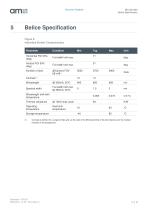
Document Feedback 5 Belice Specification Figure 6: Individual Emitter Characteristics Horizontal FOI 50% (deg) Vertical FOI 50% (deg) Number of dots Full width half max. Full width half max. Spectral width Full width half max @ 350mA, 25°C Wavelength shift with temperature Thermal resistance @ 100% duty cycle Operating Heat sink ^ (1) Contrast is defined for a single emitter grid, as the ratio of the 95th percentile of the dot intensity over the median intensity of the background.
Open the catalog to page 8
Document Feedback Figure 7: Other General Characteristics (pair of emitters) Light Source Pattern Rotation Each element of a BELICE pair Dimensions (X Y Z) (mm3) (Single emitter) Electrical contacts Number of electrical contacts Assembly type VCSEL Type A (5°) ±1.5° (testing value) Type B (15°) ±1.5° (testing value) Type A/B 3.5 x 3.4 x 3.56 Type A/B Anode and cathode on backside 1x cathode and 1x anode Reflow compatible
Open the catalog to page 9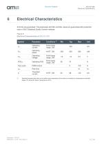
Document Feedback Electrical Characteristics All limits are guaranteed. The parameters with Min and Max values are guaranteed with production tests or SQC (Statistical Quality Control) methods. Figure 8: Electrical Characteristics of BELICE-850 Symbol Operating current Entire temp. range, CW Operating power Operating voltage Entire temp. range, CW Entire temp. range, CW Duty cycle Rise time Threshold current Specified temperatures refer to the emitter case temperature (the emitter is mounted on a temperature-controlled stage); RT stands for Room Temperature (25°C)
Open the catalog to page 10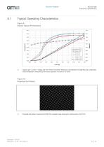
Document Feedback Typical Operating Characteristics Figure 9 : Electro-Optical Performance Typical Light - Current – Voltage and PCE (Power Conversion Efficiency) Characteristics of single BELICE configuration versus temperature. Measured at continuous operation, mounted on Cu block. Figure 10: Projected Dot Pattern Projected dots pattern measured from BELICE (cropped image showing the central portion of the FOI)
Open the catalog to page 11
Document Feedback Imaging Setup For the pattern characterization, the output is projected onto a white, matte-finished target board (Lambertian surface), at a distance. Images are taken inside a dark chamber with a monochrome CCD camera and a wide angle objective. Hotspot Detection Every individual BELICE emitter is inspected during production to detect the presence of hotspots and similar non-uniformities that cause excessive brightness of the infrared pattern and could be harmful to the human eye.
Open the catalog to page 12
Document Feedback 7 Mechanical DrawingsFigure 11: Package Dimensions Top View (Type B) Bottom View (for both types A and B) Side View (for both types A and B) (1) Outline dimensions of individual BELICE emitters Type A and B (2) All dimensions in mm
Open the catalog to page 13
Document Feedback 3D view with Fiducials for distinguishing between type A and B Figure 13: Optical Aperture Optical aperture dimensions (defining the opening where the light is emitted through) All dimensions in mm
Open the catalog to page 14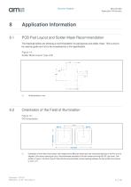
Document Feedback 8 Application Information 8.1 PCB Pad Layout and Solder Mask Recommendation The drawings below are showing a recommendation for pad layouts and solder mask. This is only to be used as guide and not to be considered as a firm specification. Figure 14: Solder Mask Layout Type A/B (1) Orientation of the Field of Illumination with respect to the BELICE emitter pair (the Horizontal direction of the FoI is to be aligned to the stereo camera pair axis). Recommended assembly of the two emitters forming BELICE (top view). One emitter is Type A, the other Type B. Note that the recommended...
Open the catalog to page 15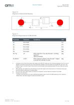
Application Information Figure 17: Alignment Requirements for BELICE-850 Unit Parameter Tolerance Conditions Ax Ay Az ©x ©y ©z Top Not critical Not critical Not critical Not critical Not critical ±2° mm deg deg When aligned to Top side fiducials(3)(emitting deg aperture) (Recommended) When aligned to Bottom side fiducials(3)(edges deg of anode and cathode Cu pad) (1) Orientation of the Field of Illumination with respect to the BELICE emitter pair (the Horizontal direction of the FoI is to be aligned to the stereo camera pair axis). Recommended assembly of the two emitters forming BELICE (top...
Open the catalog to page 16All AMS catalogs and technical brochures
 TDC-GP21
91 Pages
 NanEye / NanEye Stereo
33 Pages
 CMV50000
138 Pages
 CMV20000
48 Pages
 CMOSIS company brochure
3 Pages
 CHR70M
2 Pages
 CMV20000
2 Pages
 CMV12000
2 Pages
 CMV4000
2 Pages
 CMV2000
2 Pages


- Temperature probe
- Resistance temperature sensor
- Proximity switch
- Signal amplifying integrated circuit
- Position transducer
- Thermocouple temperature transducer
- Inductive proximity sensor
- Linear position transmitter
- Analog position transducer
- No-contact position sensor
- Compact temperature probe
- Magnetic position sensor
- Industrial converter
- High-temperature temperature sensor
- Industrial position sensor
- Digital temperature sensor
- Metal position sensor
- Potentiometer position sensor
- Voltage amplifier
- Absolute position sensor