
- Catalogs
- ams Sensors Germany GmbH
- Data sheet MTCS-C2 with JENCOLOR color sensors


Data sheet MTCS-C2 with JENCOLOR color sensors

1 / 21 PagesView full catalog
Data sheet MTCS-C2 with JENCOLOR color sensors
Product catalog summary
Introduction
The document introduces the MTCS-C2, a hardware solution for industrial color detection and measurement developed by MAZeT. It uses JENCOLOR sensors that mimic human eye perception with the RGB method, complying with DIN 5033 standards. The MTCS-C2 board integrates a color sensor IC, signal processing, interface, and measurement control, and is adaptable for design-in projects. It includes PC software for sensor calibration and measurement output in CIE Lab color space.
The document introduces the MTCS-C2, a hardware solution for industrial color detection and measurement developed by MAZeT. It uses JENCOLOR sensors that mimic human eye perception with the RGB method, complying with DIN 5033 standards. The MTCS-C2 board integrates a color sensor IC, signal processing, interface, and measurement control, and is adaptable for design-in projects. It includes PC software for sensor calibration and measurement output in CIE Lab color space.
Specifications
The MTCS-C2 package includes the board, documentation, optional USB cable, PC software "colorimeter2.exe" with USB drivers, and an optional macro function library. System requirements include a PC with at least a Pentium 150 MHz processor, 8 MB RAM, 5 MB free disk space, a USB 2.0 port, and Windows XP/2000.
The MTCS-C2 package includes the board, documentation, optional USB cable, PC software "colorimeter2.exe" with USB drivers, and an optional macro function library. System requirements include a PC with at least a Pentium 150 MHz processor, 8 MB RAM, 5 MB free disk space, a USB 2.0 port, and Windows XP/2000.
Installation and Setup
Installation involves running setup.exe to install the software and drivers. The USB driver files "usbcolor2.inf" and "usbio.sys" are copied to specific directories. The MTCS-C2 connects to the PC via USB, and the Windows device manager should recognize it as a new device. Manual directory specification may be required if automatic installation fails.
Installation involves running setup.exe to install the software and drivers. The USB driver files "usbcolor2.inf" and "usbio.sys" are copied to specific directories. The MTCS-C2 connects to the PC via USB, and the Windows device manager should recognize it as a new device. Manual directory specification may be required if automatic installation fails.
Hardware Details
The MTCS-C2 board includes a True-Color Sensor MTCSiCS, a transimpedance amplifier MTI04CQ, a microcontroller C8051F321 with a 10-bit ADC and USB interface, and EEPROM for data storage. The microcontroller manages sensor signal processing, EEPROM data storage, and USB communication.
The MTCS-C2 board includes a True-Color Sensor MTCSiCS, a transimpedance amplifier MTI04CQ, a microcontroller C8051F321 with a 10-bit ADC and USB interface, and EEPROM for data storage. The microcontroller manages sensor signal processing, EEPROM data storage, and USB communication.
Software Operation
The software is initiated via "mtcs.exe". It includes an ini-file "conf.ini" for setting basic functions, which should not be altered without consultation. The software supports multiple devices, serial interface selection, and Excel integration for data logging. Upon successful USB communication, the software displays the firmware revision and opens the main measurement window.
The software is initiated via "mtcs.exe". It includes an ini-file "conf.ini" for setting basic functions, which should not be altered without consultation. The software supports multiple devices, serial interface selection, and Excel integration for data logging. Upon successful USB communication, the software displays the firmware revision and opens the main measurement window.
Color Detection and Measurement
The main window visualizes color measurements in various formats: XYZ color values, Yxy chromaticity diagram, CIE 1976 L*a*b* color space, and L*u*v* color space. Accurate interpretation of color values requires board calibration against a standard.
The main window visualizes color measurements in various formats: XYZ color values, Yxy chromaticity diagram, CIE 1976 L*a*b* color space, and L*u*v* color space. Accurate interpretation of color values requires board calibration against a standard.
Technical Documentation Overview
The document provides detailed instructions and specifications for the MTCS-C2 system, focusing on measurement operations, data storage, system configuration, and calibration processes.
The document provides detailed instructions and specifications for the MTCS-C2 system, focusing on measurement operations, data storage, system configuration, and calibration processes.
Measurement Operations
The system allows starting and stopping measurements via the "Measurement On/Off" button. The delay time between measurements can be adjusted, affecting the overall measurement time depending on other settings like averaging and system performance.
The system allows starting and stopping measurements via the "Measurement On/Off" button. The delay time between measurements can be adjusted, affecting the overall measurement time depending on other settings like averaging and system performance.
Data Storage
Data can be saved as single values or continuous logs in a .csv file. The file format includes headers with device information and measurement data separated by semicolons. Users can choose to append new data to an existing file or create a new one.
Data can be saved as single values or continuous logs in a .csv file. The file format includes headers with device information and measurement data separated by semicolons. Users can choose to append new data to an existing file or create a new one.
Graphical Display
The system offers graphical representation options in Yxy, L*a*b*, and L*u*v* formats. Users can clear the graph or adjust the display scale. The serial number and device selection options are available if multiple devices are connected.
The system offers graphical representation options in Yxy, L*a*b*, and L*u*v* formats. Users can clear the graph or adjust the display scale. The serial number and device selection options are available if multiple devices are connected.
Menu Functions
The menu provides options for saving values, visualizing color patches, accessing configuration files, and exiting the program. The "Color Patch" feature displays measured colors with RGB values.
The menu provides options for saving values, visualizing color patches, accessing configuration files, and exiting the program. The "Color Patch" feature displays measured colors with RGB values.
Configuration Files
Configuration files (.cfg) store system settings and calibration data. The document outlines the file structure and the process for loading and saving configurations.
Configuration files (.cfg) store system settings and calibration data. The document outlines the file structure and the process for loading and saving configurations.
System Configuration
System configuration involves setting measurement parameters, environmental conditions, and calibration matrices. The process is necessary for initial setup or when changing measurement types.
System configuration involves setting measurement parameters, environmental conditions, and calibration matrices. The process is necessary for initial setup or when changing measurement types.
Calibration
Calibration is performed using known target sets to determine system offsets and correction matrices. The process involves loading standard XYZ values and measuring RGB values on a calibrated monitor.
Calibration is performed using known target sets to determine system offsets and correction matrices. The process involves loading standard XYZ values and measuring RGB values on a calibrated monitor.
Important Notes
The document emphasizes the preliminary nature of the information and reserves the right for technical changes. It also highlights potential discrepancies in color representation due to different display types and settings.
The document emphasizes the preliminary nature of the information and reserves the right for technical changes. It also highlights potential discrepancies in color representation due to different display types and settings.
Technical Specifications and Procedures
The document outlines the calibration process for the MTCS-C2 sensor. The sensor is calibrated by setting it to measure a reflective target color, and the actual value is recorded upon confirmation. If errors occur, the last measurement can be deleted and repeated. Calibration can be interrupted and returned to the 'System Configuration' interface.
The document outlines the calibration process for the MTCS-C2 sensor. The sensor is calibrated by setting it to measure a reflective target color, and the actual value is recorded upon confirmation. If errors occur, the last measurement can be deleted and repeated. Calibration can be interrupted and returned to the 'System Configuration' interface.
Continuous Calibration
If continuous calibration is set (Wait=0 in conf.ini), it can be stopped using the ESC key. After recording all 24 actual values, data is saved, and offset values are calculated. Existing actual value files can be loaded via 'Load RGB Values'.
If continuous calibration is set (Wait=0 in conf.ini), it can be stopped using the ESC key. After recording all 24 actual values, data is saved, and offset values are calculated. Existing actual value files can be loaded via 'Load RGB Values'.
Matrix Calculation
Once offset-corrected actual values are available, the 'Calculate Matrix' button is activated. Clicking it computes the correction matrices, completing the calibration. The software returns to 'System Configuration', displaying the offset values and matrices.
Once offset-corrected actual values are available, the 'Calculate Matrix' button is activated. Clicking it computes the correction matrices, completing the calibration. The software returns to 'System Configuration', displaying the offset values and matrices.
Lighting Specification
For calculated Lab values, specify the lighting type used during calibration ('L*a*b*Light').
For calculated Lab values, specify the lighting type used during calibration ('L*a*b*Light').
Data Storage
Calibration data is stored in on-board memory via 'Write to Memory', ensuring availability after each restart without recalibration.
Calibration data is stored in on-board memory via 'Write to Memory', ensuring availability after each restart without recalibration.
Contact Information
For further information, contact MAZeT GmbH at Göschwitzer Straße 32, 07745 Jena, Tel: +49 3641 2809-0, Fax: +49 3641 2809-12, Email: [email protected], Website: http://www.MAZeT.de
For further information, contact MAZeT GmbH at Göschwitzer Straße 32, 07745 Jena, Tel: +49 3641 2809-0, Fax: +49 3641 2809-12, Email: [email protected], Website: http://www.MAZeT.de
See more
Catalog excerpts
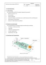
2 Bei Bestellungen sind die Komponenten zur Lieferung in der Bestellung einzeln aufzuzhlen. size="-1">
Open the catalog to page 3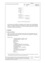
MTSCiCSFarbsensor MTI04CSTransimp.Verstrker C8051F321 Controller mit AD-Wandlerund EEPROM USB Interface Spannungs- versorgung > 5 Die hier nicht beschriebenen Parameter bitte nicht ohne Rcksprache 伤ndern. Die Eintragungen in Ini-File unter [COLORIMETER2] und [modEVA] drfen ebenfalls nicht gendert werden. size="-1">
Open the catalog to page 6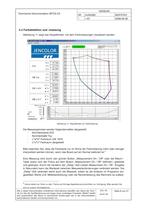
- - - - > 6 Gerne stellen wir Ihnen zu dem Thema auf Anfrage Appikations(vor)schriften zur Verfgung. Bitte wenden Sie sich an unsere Vertriebsbros. size="-1">
Open the catalog to page 9All Ams Sensors Germany GmbH catalogs and technical brochures
 Company Brochure
20 Pages
 EMS Services incl. Design
2 Pages
 MTCS-C3
2 Pages
 ASIC Design Service Guide
4 Pages
 JENCOLOR
2 Pages
 Redesign of obsolete ASICs
2 Pages
 MAZeT Flyer
2 Pages
 JENCOLOR Flyer
2 Pages
 JENCOLOR- True Color Sensors
2 Pages
 MAZeT GmbH company facts
20 Pages


Archived catalogs
 MRGBiCS
9 Pages
 MRGBiCT
7 Pages
 Data Sheet - MTCSiCS
8 Pages
 Data Sheet - MTCS-ME1
25 Pages
 Software Description MTCS-ME1
20 Pages
 Data Sheet - MTI04
12 Pages
 Product information - MCS3
2 Pages
 Data sheet - MCS3AS
7 Pages
 Data Sheet - MCS3AT/BT
7 Pages
 MAZeT flyer
2 Pages





*Prices are pre-tax. They exclude delivery charges and customs duties and do not include additional charges for installation or activation options. Prices are indicative only and may vary by country, with changes to the cost of raw materials and exchange rates.
About DirectIndustry
DirectIndustry is a marketplace that offers B2B players a complete experience, from product sourcing to purchase. DirectIndustry is an entity of VirtualExpo Group.
Are you a buyer?
Are you a supplier?