
Catalog excerpts

Detect and Alert Equipment Operators of the Presence of Metal Particles
Open the catalog to page 1
NASA Reliability Centered Maintenance Guide for Facilities and Collateral Equipment occurring. Figure 8—1 illustrates the relationship between wear particle size, concentration and equipment condition. Wear Particle Size 1)1 m) Figure 8-1. Wear Particle Size and Equipment Condition
Open the catalog to page 2
Why should you use MPD? 3 • How the oil is affected- Particles, especially catalytic metal ones like copper, iron and lead increase the rate at which oxidation occurs. Numerous minute particles in stable suspension can cause the oil's viscosity to increase. Oil gets stripped of its: • • • • • • polar additives anti-wear additives extreme pressure additives rust inhibitors dispersants How the machine is affected- Abrasive particles are responsible for much of the wear leading to premature failure of mechanical components. Under sliding conditions, clearance-sized particles enter the oil film...
Open the catalog to page 3
Eliminate costly repairs 4 • Insures against costly parts and repairs • Replace a bearing instead of a crankshaft! • Proactive Maintenance Tool • Minimize down time! • • • • • • Verifies filter performance and failures Permits “on-condition” lab oil analysis Confirms systems flushing Identifies botched machine repairs Detects high corrosion and abrasion wear conditions Confirms corrective maintenance
Open the catalog to page 4
Features & Benefits 5 • Unique, Grid Sensing Technology • Detects all conductive particles • Metal particles and chips • Non magnetic particles • Plated grid resists lacquering • Oil and electrical compartments positively sealed from each other • Improve electrical isolation • UL Version • • • • Approved for Class 1, Div. 1, Groups B,C, & D Meets National Electric Code 316 S.S. Body Meets API 614
Open the catalog to page 5
What industry uses MPD? 6 If you have metal particles in non-conductive fluid lubrication systems, you need MPD. • • • • • • • • Gas compression/pipeline/gas plants Power plants/utilities Marine Industry Food Industry Refrigeration Mining Industry Oil and Gas platforms Wind farms
Open the catalog to page 6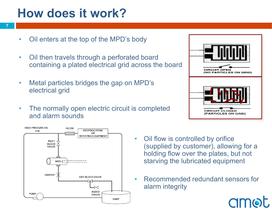
How does it work? 7 • Oil enters at the top of the MPD’s body • Oil then travels through a perforated board containing a plated electrical grid across the board • Metal particles bridges the gap on MPD’s electrical grid • The normally open electric circuit is completed and alarm sounds • Oil flow is controlled by orifice (supplied by customer), allowing for a holding flow over the plates, but not starving the lubricated equipment • Recommended redundant sensors for alarm integrity
Open the catalog to page 7
FAQ 9 • Q: What size particles will the MPD detect? • A: Any accumulation of metal shavings, flakes or chips which can bridge the gap between the MPD’s grid. • Q: Are grids available with different size spaces between the grid? • A: AMOT will customize special grid boards with smaller or larger spaces than the 1/6” standard space • • AMOT’s experience indicates 1/16” spacing is optimum for 95%+ applications Set up charges for custom grid board
Open the catalog to page 9
FAQ 10 • Q: What types of metals will the MPD detect? Does the metal have to be magnetic (ferrous)? • A: The MPD will detect all metal particles which are conductive; the particles do not have to be magnetic. • • • • • • Steel Aluminum Babbit Stainless Steel Bronze Tin • Q: Does the MPD detect water in oil? • A: MPD does not detect water in oil. However, AMOT can provide water in oil detection monitor.
Open the catalog to page 10
FAQ 11 • Q: What is the flow rating for the MPD? • A: Cv (flow coefficient) for the MPD is 4.34. Generally speaking, the MPD’s outlet flow should be controlled to limit the oil flow to 10% of the oil pumps capacity. • For reference, the maximum flow thru MPD at 60 psi is 27 GPM of 180 SSU oil, specific gravity .90, with no restriction on its outlet port.
Open the catalog to page 11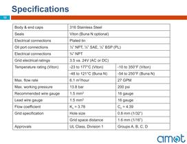
Specifications 12 Body & end caps 316 Stainless Steel Seals Viton (Buna N optional) Electrical connections Plated tin Oil port connections ½” NPT, ½” SAE, ½” BSP (PL) Electrical connections ¾” NPT Grid electrical ratings 3.5 va. 24V (AC or DC) Temperature rating (Viton) -23 to 177°C (Viton) -10 to 350°F (Viton) -48 to 121°C (Buna N) -54 to 250°F (Buna N) Max. flow rate 6.1 m3/hour 27 GPM Max. working pressure 13.8 bar 200 psi Recommended wire gauge 1.5 mm2 16 gauge Lead wire gauge 1.5 mm2 16 gauge Flow coefficient Kv = 3.78 Cv = 4.39 Grid specification Hole size 0.8 mm (1/32”) Grid space...
Open the catalog to page 12All AMOT catalogs and technical brochures
-
IP1-Impact-Transmitter
2 Pages
-
7001 Swing Gate
4 Pages
-
4095 2-Way Vent Valve
1 Pages
-
4395 Electric Trip Switch
4 Pages
-
4103D Temperature Detector
4 Pages
-
1672 Pressure Sensing Valve
7 Pages
-
4047 Pressure Valve
5 Pages
-
4109 Vibration Sensor
7 Pages
-
Model 8402
6 Pages
-
Model 4123C
5 Pages
-
Model 4418F
9 Pages
-
Model 4420
7 Pages
-
Model 2180
6 Pages
-
XTS-W Bearing Wear Monitor (BWM)
11 Pages
-
SEDM
4 Pages
-
Control System Solutions
12 Pages
-
Chalwyn Spark Arrestors
4 Pages
-
System Selection Guide
12 Pages
-
Product Selection Guide
20 Pages
-
Intake Air Shutoff Valve
4 Pages
-
Temperature Control Valve
21 Pages
-
Metal Particle Detector
8 Pages
-
2 or 3-Way Pressure Valve
5 Pages


