- Catalogs
- Ametek Land
- OPACITY AND PM MONITORING IN EMISSION STACKS
- Company
- Products
- Catalogs
- News & Trends
- Exhibitions
OPACITY AND PM MONITORING IN EMISSION STACKS
1 /12Pages

OPACITY AND PM MONITORING IN EMISSION STACKS
1 /12Pages
Catalog excerpts

EMISSION STACKS
Open the catalog to page 1
INTRODUCTION Smoke and dust emissions from industrial plants, such as coal-fired power stations and industrial incinerators, damage the environment and pose a health hazard to humans. of small particles on human health are a major source of respiratory disorders. Therefore, minimising the emissions from industrial stacks remains a goal, driving ever greater reductions in emissions. Subsequently these emissions are regulated by government agencies across the world. These include the Environmental Protection Agencies (EPA) in the USA and the UK. Globally, government agencies recognise the need...
Open the catalog to page 2
OPACITY, PM AND LIGHT SCATTERING Opacity is defined under the ASTM D6216 standard as the degree to which PM emissions reduce the intensity of transmitted photopic light (due to absorption, reflection and scattering) and obscure the view of an object through ambient air, an effluent gas stream, or I0 an optical medium, of a given pathlength. These processes are illustrated in Figure 1, which shows some of the light rays passing through the sample, while others are scattered, absorbed or reflected. Figure 1: Loss through scattering, absorption and reflection Figure 2 Loss through scattering, absorption...
Open the catalog to page 3
REGULATORY COMPLIANCE: OPACITY AND PM CONCENTRATION Some regulatory bodies set the ELV in terms of the plume opacity at the stack exit. In these cases, the ELV will typically be 10% or 20% opacity, and the plant operator will be fined if emissions are above this level. In other cases, the ELV will refer to the mass concentration of PM emitted from the stack, and the ELV will be expressed as a mass concentration in the form 10 mg/m3 or 50 mg/m3. The US EPA has traditionally set emission limits as percentage opacity, but more recent rules have shifted to mass concentration units. European regulators...
Open the catalog to page 4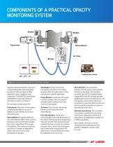
COMPONENTS OF A PRACTICAL OPACITY MONITORING SYSTEM Figure 5: Components of the AMETEK Land Model 4500 MkIII Typically Opacity Monitors consist of a transmissiometer and associated equipment that provides reliable operation, easy installation and calibration. The AMETEK Land Model 4500 MkIII incorporates all these elements as shown in Figure 5 The principal components are: Transceiver: The heart of the system, containing the light source and detectors, user interface and main microprocessor. Retroreflector: A passive reflector, the retroreflector differs from a mirror because it returns the light...
Open the catalog to page 5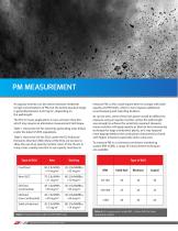
PM MEASUREMENT An opacity monitor can be used to measure moderate to high concentrations of PM, but the lowest practical range is generally between 0-20 mg/m3, depending on the pathlength. The ELV for many applications is now set lower than this, which may require an alternative measurement technique. Table 1 shows the ELV for electricity generating units (EGUs) under the latest US EPA regulations. Table 2 shows the ELV for EGUs under the EU Industrial Emissions Directive (IED). Many of the ELVs are too low to allow the use of an opacity monitor. Users in the US are, in many cases, usually reluctant...
Open the catalog to page 6
LASER BACK-SCATTERING In this process, a laser shines into the flue and a lens collects the back-scattered light which is focused onto a detector. The scattered light intensity can be correlated with the dust concentration. Figure 6: Laser back-scattering This is an attractively simple technique and, unlike an opacity monitor, only needs to be installed on one side of the stack. However, it has a number of limitations: • The measurement can be made quite close to the stack wall, so it may not be a truly representative measurement • The back-scattered signal can be quite weak, so it is less sensitive...
Open the catalog to page 7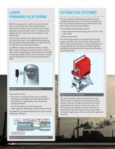
LASER FORWARD-SCATTERING With this arrangement, a probe is inserted into the stack. A laser shines down the probe and into a measurement region. A lens or mirror at the end of the probe collects the light, which is scattered a few degrees off-axis, and returns it to a detector in the probe head. Like the other systems, this requires access to just one side of the stack. Low-angle forward-scattering also provides the strongest signal, so it gives the best sensitivity for low-level measurements. In addition, changes in particle size have a smaller effect on this technique compared to back-scatter...
Open the catalog to page 8
TRIBOELECTRIC (ELECTRODYNAMIC) PROBE The inherent sensitivity of charge transfer devices allow them to be used where dust concentrations are very low (typicallyafter bag filters) and can also provide a good indicator of a bag filter’s performance. Some more advanced charge transfer systems can be used as a PM-CEMS and can be quantified to measure dust concentration complying to environmental regulatory requirements. A baghouse is a highly efficient method for removing PM from flue gases as long as all of the bags remain in good condition. However, as the bags age they begin to leak and allow...
Open the catalog to page 9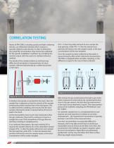
CORRELATION TESTING Nearly all PM-CEMS, including opacity and light-scattering devices, use inferential methods which measure a quantity related to dust density. In order to determine the actual PM concentration, they need to be calibrated for the specific installation conditions by correlating the monitor output with the result of a standard reference method. The details of the standard reference methods may differ, but all are based on measurements of a dust sample, collected isokinetically by a skilled stack tester or test team. Flowmeter Flow Regulator Sample Velocity = Gas Velocity Figure...
Open the catalog to page 10
A series of measurements is taken under different process operating conditions, and the resulting analyser output plotted against the simultaneously measured reference method data. Both PS-11 (the US performance standard for continuous PM monitors) and EN 13284:2 (the EU calibration methodology for continuous PM monitors) require a minimum of 15 valid data points, though the criteria for rejecting invalid data differ between the two methods. correlation curve. Assuming this data passes the test, the correlation curve is programmed into the gas analyser and the system can be used to make valid...
Open the catalog to page 11All Ametek Land catalogs and technical brochures
 MWIR-BORESCOPE-640
4 Pages
 CYCLOPS L
4 Pages
 4750-PM PM-CEMS DUST MONITOR
4 Pages
 High Temperature Measurement
2 Pages
 4200+OPACITY MONITORING
4 Pages
 4650-PM
4 Pages
 AUTO POUR
4 Pages
 SLAG DETECTION SYSTEM
5 Pages
 SPOT actuator
5 Pages
 NIR BORESCOPE GLASS
4 Pages
 ametek land dtt brochure
2 Pages
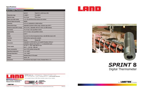 SPRINT 8
2 Pages
 PRODUCT GUIDE
8 Pages
 SPOT Thermometer
4 Pages
 SPOT Family
8 Pages
 Landcal Calibration Sources
8 Pages
 Cyclops Logger Software
4 Pages
 ARC Imager
4 Pages
 LANDSCAN TCP/IP Communications
52 Pages
 NIR Thermal Camera
4 Pages
 NIR BORESCOPE 3XR
4 Pages
 NIR-B Thermal
2 Pages
 Calibration Furnaces
8 Pages
 ARC Thermal Imaging Camera
2 Pages
 NIR BoreScope
2 Pages
 iQ Series Spot Thermometer
2 Pages
 SPRINT 8 Digital Thermometer
2 Pages
 SOLOnet Digital Thermometers
8 Pages


Archived catalogs
- Kiln
- Digital imager
- Actuator
- Gas analyzer
- Heat treatment kiln
- Industrial camera module
- Automation software solution
- Management software solution
- Concentration analyzer
- Monitoring analyzer
- Electric actuator
- Analysis software solution
- Liquids analyzer
- LAND infrared camera
- Measuring machine
- Monitoring camera system
- Automatic analyser
- LAND Windows software
- Real-time software
- Control software