- Catalogs
- AMETEK Factory Automation
- Gemco 2006 Rotary Limit Switch Datasheet
Gemco 2006 Rotary Limit Switch Datasheet
1 /7Pages

Gemco 2006 Rotary Limit Switch Datasheet
1 /7Pages
Catalog excerpts

2006 Series Geared Rotary Limit Switches SUPERIOR DESIGN AND OPERATING FEATURES Quality parts make each Geared Rotary Limit Switch highly dependable. • he limit switch’s ½" input shaft is connected to a worm gear. Adjustable self-lubricating nylon T roller-cams are concentrically mounted to the worm gear. These adjustable cams actuate the precision limit switches by utilizing a lever assembly. • ach Rotary Limit Switch can be provided with up to 4 switches and can be rotated clockwise E or counterclockwise. • EMA 4 /5 Rugged Cast Aluminum enclosure N • " Input Shaft with Woodruff Key for quick drive connection ½ • elf-lubricating Bearings – Powdered metal impregnated bearings for life-time lubrication S • tandard ratios range from 5:1 to 1080:1. S • xternal Mounting holes, permit mounting without internal interference E • Bronze gears and Nylon cams for longevity • emco rugged duty precision Snap Action Switches – SPDT or DPDT with Isolated Contacts G UL Recognized • o minimum speed is specified because snap action contacts are used. Maximum rated speed N of the input shaft is 2,000 RPM. • asy to wire terminals E • aximum Operating temperature -40°F to 180°F (-40°C to 82.2°C). M • SA & CE rated electrical switches available upon request C • ptional - Potentiometer output or Pneumatic Switches available upon request O DESCRIPTION AMETEK Factory Automation markets, engineers, and manufactures sensors and controls for demanding and harsh industrial environments. The Gemco® Geared Rotary Limit Switches are primarily used in material handling and rotary operations where motion is expressed in shaft rotation. The input shaft is typically connected to the motor or drive mechanism, after a set amount of turns, the cam trips the switches, thus starting or stopping the movement. The primary purpose of the switch is to control the intermediate or end limits in linear or rotary motion. The switch is often used as a safety device to protect against accidental damage to equipment due to over-travel. Our Geared Rotary Limit Switch line is designed for longevity. Units include all metal gearing and switches that are rated for 15 million operations. In the 2006 Series (General Purpose) Watertight / Oil tight / Dust tight NEMA 4 / 5 enclosures are made of cast aluminum with ½” input shaft. External mounting holes enable switch mounting without internal interference. Available in 2 or 4 circuit units with either SPDT or DPDT switches, with ratios from 5:1 to 1080:1. Optional Potentiometers are available in our two circuit models for continuous feedback. The NEMA 4 / 5 enclosure provides a clean environmental condition for the industrial duty snap action switches. When motion can be expressed in shaft rotation, either through a roller chain, gear train, or direct coupling, the Gemco® 2006 Series Geared Rotary Limit Switch makes it possible to open or close, up to four independent circuits at the desired angular positions. Superior Design and Operating Features All Metal Gearing for Longevity
Open the catalog to page 1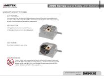
2006 Series Geared Rotary Limit Switches SIMPLICITY IS THE KEY TO SUCCESS EASY TO INSTALL This limit switch may be mounted in any orientation. External mounting holes enable switch mounting without internal interface. When installed properly, this limit switch will provide long life with a minimum amount of service or maintenance. EASY TO SET-UP 1. Simply loosen set screw to unlock the cam. 2. Then adjust thumb screw to desired trip point. EASY TO WIRE Screw head terminals for easy wiring EASY TO MAINTAIN The limit switch was lubricated at the factory and should not require lubrication for the...
Open the catalog to page 2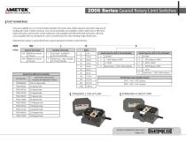
AMETEK SENSORS, TEST & CALIBRATION 2006 Series Geared Rotary Limit SwitchesPART NUMBERING Units are available in 2 or 4 circuit models. Number of circuits, ratio, shaft extension and switch type are all configured in part number structure. Two circuit assemblies are available in either right hand or left hand shaft extensions, whereas four circuit models are only available with left hand shaft extensions. All units come supplied with our standard 25° cams. Consult factory for units needing longer dwell cams. Potentiometer output or special dwell cams, require special part number. Consult Factory....
Open the catalog to page 3
SENSORS, TEST & CALIBRATION 2006 Series Geared Rotary Limit Switches 2 CIRCUIT UNIT WITH POTENTIOMETER (2 CAMS & POTENTIOMETER) -USES 4 CIRCUIT SIZE ENCLOSURE Potentiometer - Optional An optional feature of mounting a 2-watt multi-turn potentiometer within the enclosure, and gear coupled to the input shaft, is offered. This feature permits the potentiometer to be used as a remote position indicator or as a constant output auxiliary control device for open or closed loop feedback systems. • Available in NEMA 4, 4 circuit style enclosures • Two SPDT or DPDT switches and potentiometer • Consult...
Open the catalog to page 4
2006 Series Geared Rotary Limit Switches DIMENSIONS 2006-402 (2 CIRCUIT RIGHT OR LEFT HAND DIMENSIONS) 2006-404 (4 CIRCUIT LEFT HAND DIMENSIONS) AUTOMATION & PROCESS TECHNOLOGIES Z440.D1R 2006 RCLS Data Sheet Page 5 of 7
Open the catalog to page 5
2006 Series Geared Rotary Limit Switches DIMENSIONS 2006-402 (2 CIRCUIT LEFT HAND DIMENSIONS WITH RIGHT ANGLE GEAR REDUCER) 2006-404 (4 CIRCUIT LEFT HAND DIMENSIONS WITH RIGHT ANGLE GEAR REDUCER) Z440.D1R 2006 RCLS Data Sheet Page 6 of 7
Open the catalog to page 6
AMETEK® SENSORS, TEST & CALIBRATION 2006 Series Geared Rotary Limit SwitchesSPECIFICATIONS Enclosure Nominal Input shaft to Cam Ratio ELECTRICAL SWITCH RATINGS Electrical Contact Ratings NOTE: The maximum period for which the switch contacts are opened or closed during one revolution (360°) of the cam block assembly is 25° or 335°. Multiply the gear ratio times 25° or 335° to obtain the input shaft rotation which will yield 25° or 335° of cam block rotation. Must be Same Polarity SINGLE POLEDOUBLE THROW Mtg. Holes for #6 Screws DOUBLE POLEDOUBLE THROW Mtg. Holes For #6 Screws Must be Same Polarity...
Open the catalog to page 7All AMETEK Factory Automation catalogs and technical brochures
 956 eBlok
8 Pages
 958A
958A6 Pages
 Motogard Series
4 Pages
 7330X Series
2 Pages
 7330 V Series
2 Pages
 7330 S & F Series
2 Pages
 7330 EX/ED Series
2 Pages
 Industrial Brakes
2 Pages
 957
9576 Pages
 Linear Displacement Transducers
86 Pages
 950IS
950IS3 Pages
 CATRAC & SnapTrac Catalog
32 Pages
 B/W Controls Catalog
56 Pages


Archived catalogs
 1980 Rotating Cam Limit Switch
20 Pages
 953A/D/SSI VMAX Gemco LDT
6 Pages
 950MD Gemco LDT
1 Page
 955S Smart BRIK
2 Pages
 952 BlueOx Gemco LDT
9 Pages
 955LC Brik
2 Pages
 1986DN - DeviceNet Resolver
2 Pages
 955D BRIK Gen III Gemco LDT
2 Pages
 955A Brik Gemco LDT
2 Pages
 925 Cable Reel Sensor
8 Pages
 Linear Cable Reel Sensor
8 Pages
 RESOLVER CATALOG
20 Pages


- LED monitor
- Liebherr level sensor
- Liebherr liquid level sensor
- Protection relay
- Liebherr position sensor
- Liebherr friction brake
- Liebherr analog level sensor
- Liebherr linear position sensor
- Liebherr control pedal
- Liebherr displacement sensor
- Liebherr single pedal pedal
- Rugged monitor
- Electronic pedal
- Liebherr storage tank level sensor
- Liebherr linear displacement sensor
- Liebherr analog position sensor
- Liebherr disc brake
- Liebherr spring brake
- Liebherr electromagnetic brake