- Catalogs
- AMETEK Drexelbrook
- Unifloat Level Sensors
- Company
- Products
- Catalogs
- News & Trends
- Exhibitions
Unifloat Level Sensors
1 /9Pages

Unifloat Level Sensors
1 /9Pages
Catalog excerpts

Ordering Guide & Technical Information Unifloat Level Sensors ABSOLUTE PROCESS CONTROL KNOW WHERE YOU ARE... REGARDLESS
Open the catalog to page 1
SENSORS, TEST & CALIBRATION Series 7014Unifloat™ Level Sensors DESCRIPTION The BIW Unifloat level sensing system was developed especially to permit simple, low-cost installation and ease of adjustment in service for a broad range of applications requiring accurate multiple function/multiple level control of any type of liquid. FOUR BASIC COMPONENTS As illustrated at left, this advanced new system consists of just four basic components: (1) A single MAGNETIC FLOAT that is free to travel up and down with the rise and fall of liquid. Standard material is 316 S.S. (2) A GUIDE TUBE of any practical...
Open the catalog to page 2
Because of its inherent simplicity, the BIW Unifloat™ Level Sensor concept provides many features and advantages not offered by other float type level sensing devices. Among them: Fewer Parts/Lower Costs—Use of one free-moving float to actuate up to 12 hermetically sealed and encapsulated reed switches eliminates expense and problems involved in mounting a separate float plus float stops at each operating level. Ease of Installation— Suspending all reed switches on a common circuit return line simplifies assembly and installation. Just slide switches up or down to desired control levels and position...
Open the catalog to page 3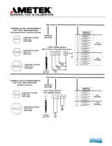
SENSORS, TEST & CALIBRATION
Open the catalog to page 4
— A* Unifloat® CATALOG NUMBERING SYSTEM--- 6-SS J HOLDER MATERIAL & SIZE Cast Iron 2" 8 3" NPT See page 54 for information regarding switch settings and direct or inverse operation. ORDERING INFORMATION 1. Specify Unifloat with a complete catalog number. 2. Specify switch setting information by including a switch specification chart from page 55. 3. Provide details on the nature of the liquid being controlled. Consult factory for lengths and'or materials not listed. -B- ■ 10-SS. GUIDE TUBE MATERIAL HOLDER MATERIAL & SIZE 316 Stainless Steel 3" NPT 5-6 Switches TUBE LENGTH: Tube will be cut...
Open the catalog to page 5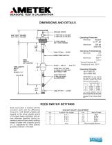
SENSORS, TEST & CALIBRATION
Open the catalog to page 6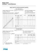
REED SWITCH SPECIFICATION CHARTS BARRIER TERMINAL BLOCK IN HOLDER No. 6 Screw — Saddle Clamp Max. Wire Size: #14 A W G TYPE C REED SWITCH (All contacts have a common ground) Maximum rating 10 watts at 120 volts AC or DC. ONE LEAD WITH GROUNDED CONTACT Up to 7 switches in 2 inch holder. Up to 12 switches in 3 inch holder. Common side of each switch must connect to grounded side of the same power supply. NOTE: Switches are installed with No. 1 as the lowest in the guide tube and working upward using the required number of switches. GUIDE TUBE LENGTH: Tube will be cut 2.75" longer than the maximum...
Open the catalog to page 7
SENSORS, TEST & CALIBRATION OTHER APPLICATIONS WITH TYPE C REED SWITCH Having Common Grounded Contact The line diagram below shows the wiring method recommended when operating conventional relays and devices rather than BIW relays. To meet UL requirements, the control power must be from an isolation transformer with the common side grounded. This means that the Unifloat switches are connected in the grounded side of the relay coils rather than the hot side. If this causes a circuit design problem, then the Type I isolated contact reed switches should be used in the Unifloat. AC Line Voltage —...
Open the catalog to page 8
MADE IN AMERICA Copyright 2013 by AMETEK Drexelbrook. All Rights Reserved. Made in the USA.
Open the catalog to page 9All AMETEK Drexelbrook catalogs and technical brochures
 Multipoint II Series
2 Pages
 ClearLine Series
2 Pages
 1500 SERIES RELAY
2 Pages
 7014 and 7010 Series
2 Pages
 Universal IV ™ CM Model
8 Pages
 Model 375
4 Pages
 Model 575 Series
5 Pages
 Model 575P
4 Pages
 Model 675
5 Pages
 Dumpstar Series
2 Pages
 Plugged Chute Detector
4 Pages
 Universal II Series
2 Pages
 Level Mate III
4 Pages
 Model 575S
5 Pages
 Model SST Slim-Line
4 Pages
 Model SDT
4 Pages
 Total Tank Level System
6 Pages
 Drexelbrook Level Measurement
16 Pages
 DR6300 Series
17 Pages
 DR5200 Series
17 Pages
 DR7000 Series
4 Pages
 Z4-Series
6 Pages
 Universal IV Sales Brochure
10 Pages
 Coal and Fly Ash Solutions
6 Pages
 RXL Series, IntelliPoint
4 Pages


Archived catalogs
 401-400 Series
4 Pages
 Model DDMC
8 Pages
 Accessories Drexelcage
2 Pages
 Point Level
5 Pages
 DR7000
4 Pages
 CM3 Series Cut Monitor
4 Pages
 701X Series Data Sheet
2 Pages
 PNT Series, ThePoint
4 Pages
 Model SDT
4 Pages
 USonic™ Series
4 Pages


- Surge protector
- Digital I/O
- AMETEK level switch
- IO module
- AMETEK liquid level switch
- Liquid level sensor
- Analog I/O
- Switching relay
- Digital IO module
- Float level switch
- Analog level sensor
- Transceiver module
- AMETEK stainless steel level switch
- AMETEK level transmitter
- AMETEK liquid level transmitter
- Electromechanical relay
- Analog IO module
- Serial I/O
- Digital output level sensor