- Catalogs
- AMETEK Drexelbrook
- 401-400 Series
- Company
- Products
- Catalogs
- News & Trends
- Exhibitions
401-400 Series
1 /4Pages

401-400 Series
1 /4Pages
Catalog excerpts
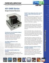
A Leader In Level Measurement Solutions 401-0400 Series Single Channel Receiver Verify™ loop diagnostics allow remote manual check and continuous selftesting. This Single Channel Receiver supplies a 4-20 mA loop to, and monitors the status of, a two-wire, on/off level control transmitter (RF, or, Ultrasonic Technology). It provides relay indication of loop status, showing loop in 1) normal, 2) alarm 3) fault condition 4) Verify test in progress. Choosing the Verify option provides a remotely activated test which completely and positively checks the spill prevention system, including the loop wiring, sensing element, and final control elements. Continuous Level Simulation Means Maximum Assurance Continuous automatic verification (high level duplication), along with manual magnetic key certification, testing the entire control loop (including final control elements) giving the ultimate in performance reliability. Two-Wire Continuous Loop Diagnostics Two-wire design allows for continuous selfchecking loop diagnostics, which check the twisted pair for open and short circuits. The system was designed for intrinsically safe outputs. Two-Wire Overall Installed Cost Savings Two-wire technology eliminates need for line power at the field transmitter and saves on costs for associated hardware. With the AutoVerify option, a test pulse occurs every ten seconds, signaling the Verify test at the transmitter and duplicating a high level condition at the sensing element. The receiver then checks that the switch has responded properly. If the switch does not respond to the test, the receiver indicates a fault condition in the output loop. The receiver provides DPDT relay output for fault indication. (NOTE: When using the Single Channel Receiver with the Two Wire IntelliPoint product, specify receiver without Verify. Verify is an onboard feature of the IntelliPoint.) The Most Complete System Testing Package Available. To test the entire control loop, and any final control elements, a Certify™ test may be activated manually at the receiver. This manual test not only tests the entire spill prevention system, but also checks that the AutoVerify selfcheck circuitry is functioning.
Open the catalog to page 1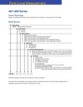
401-400 Series Proven Technology Based on reliable technology that's performed successfully at major plants for decades. Model Number Technology 401-04 Single Channel Receiver Input Power 0 120 Vac 3 240 Vac Relay Output 0 DPDT Fault and Alarm 1 DPDT Fault and Alarm with Push-button Verify™ 3 DPDT Fault and Alarm with Magnetic Verify™ 4 DPDT Fault and Alarm with AutoVerify™ and Magnetic Certify™ 5 DPDT Fault and Alarm with AutoVerify™ and Push-button Certify™ Approvals 0 No Approvals C CSA Approval F FM Approval Intrinsic Safety Barriers 0 Output is limited to 24 volts, current will supply one...
Open the catalog to page 2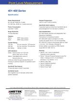
Power Requirement: 95-145 Vac, 50/60 Hz, 5 watts 215-265 Vac, 50/60 Hz, 5 watts maximum Power Consumption Less than 7 watts Surge Protection 10 Amp Standard Outputs: Alarm: Fault: DPDT relay contact DPDT relay contact Contact Rating: 120 Vac: 5A non-inductive / 3A inductive 230 Vac: 5A non-inductive / 2A inductive Min Rating 100mA/ 12 VDC LED Indication: Green: Normal when lit (14-20 mA) Alarm when out (4-10 mA) Yellow: Fault/Malfunction when lit. Normal when out. LEDs are visible through standard Nema 4X housing or optional viewport on explosion-proof housing. AutoVerify Test Interval: 10 seconds...
Open the catalog to page 4All AMETEK Drexelbrook catalogs and technical brochures
 Multipoint II Series
2 Pages
 ClearLine Series
2 Pages
 1500 SERIES RELAY
2 Pages
 7014 and 7010 Series
2 Pages
 Unifloat Level Sensors
9 Pages
 Universal IV ™ CM Model
8 Pages
 Model 375
4 Pages
 Model 575 Series
5 Pages
 Model 575P
4 Pages
 Model 675
5 Pages
 Dumpstar Series
2 Pages
 Plugged Chute Detector
4 Pages
 Universal II Series
2 Pages
 Level Mate III
4 Pages
 Model 575S
5 Pages
 Model SST Slim-Line
4 Pages
 Model SDT
4 Pages
 Total Tank Level System
6 Pages
 Drexelbrook Level Measurement
16 Pages
 DR6300 Series
17 Pages
 DR5200 Series
17 Pages
 DR7000 Series
4 Pages
 Z4-Series
6 Pages
 Universal IV Sales Brochure
10 Pages
 Coal and Fly Ash Solutions
6 Pages
 RXL Series, IntelliPoint
4 Pages


Archived catalogs
 Model DDMC
8 Pages
 Accessories Drexelcage
2 Pages
 Point Level
5 Pages
 DR7000
4 Pages
 CM3 Series Cut Monitor
4 Pages
 701X Series Data Sheet
2 Pages
 PNT Series, ThePoint
4 Pages
 Model SDT
4 Pages
 USonic™ Series
4 Pages


- Surge protector
- Digital I/O
- AMETEK level switch
- IO module
- AMETEK liquid level switch
- Level probe
- Liquid level sensor
- Switching relay
- Analog I/O
- Digital IO module
- Float level switch
- Analog level sensor
- Transceiver module
- AMETEK stainless steel level switch
- AMETEK level transmitter
- AMETEK liquid level transmitter
- Electromechanical relay
- Analog IO module
- Serial I/O
- Digital output level sensor