- Catalogs
- AMETEK Drexelbrook
- 1500 SERIES RELAY
- Company
- Products
- Catalogs
- News & Trends
- Exhibitions
1500 SERIES RELAY
1 /2Pages

1500 SERIES RELAY
1 /2Pages
Catalog excerpts

1500 SERIES RELAY DATA SHEET The Series 1500 Induction Relays provide versatile and economical means of controlling many processing and production functions from remote locations with the safety inherent in a low energy sensing circuit that is isolated from the AC power source. When installed near pumps, motors or other operating equipment, the Series 1500 Induction Relay permits use of low-cost light gauge wires for the control circuit to level sensing electrodes. Relays with low voltage secondary coils provide remote control up to 36,000 feet from contact type pilot devices. Available as open chassis units or furnished with a choice of standard enclosures, these relays are connected to a constant source of alternating current. When properly installed, they will draw a maximum of 9 volt-amperes regardless of the line or electrode circuit voltage. CAUTION: Electrodes are terminals of live electrical circuits and must be installed to prevent accidental contact by personnel. Control power must be disconnected before servicing. A GOOD DEPENDABLE RETURN GROUND CONNECTION TO LIQUID IS REQUIRED .21 SLOT 4 PLACES SPECIFICATIONS Input Voltage: 110 to 600 VAC 50/60 Hz Power Consumption: 9 Volt-Amperes Max. Contact Rating: 25 Amps Resistive at 120, 240, or 480 VAC 1 HP Single Phase at 120 or 240 VAC Heavy Duty Pilot 120 to 600 VAC 2 Amps Resistive at 120 VDC 10 Amps Resistive at 48 VDC Ambient Temperatures: -20° F to 150° F -28.8° C to 65.5° C Coil Insulation: Class "B" Output Contact Arrangement: Available in 1, 2, and 3 pole N.O. and/or N.C. configurations as shown in diagram. SECONDARY VOLTS MUST BE VERTICALLY MOUNTED AS SHOWN CONTACT ARRANGEMENT CODE MIDDLE CONTACT TERMINALS 5 & 6 SECONDARY VOLTS BOTTOM CONTACT TERMINALS 9 & 10 PART NUMBER ORDERING INFORMATION Series 1500 Contact Arrangement A, B, C, D, E, F, G, H, J (See Chart Above) Supply Line Voltage L1 (110-120 VAC 50/60 Hz), L2 (208-240 VAC 50/60 Hz), L3 (440-480 VAC 50/60 Hz), L4 (550-600 VAC 50/60 Hz), L5 (120/240) VAC 50/60 Hz) Secondary Coil Voltage S1 (12 V), S2 (24V), S3 (40V), S4 (90V), S7 (220V), S8 (360V), S9 (480V), S11 (800V) Enclosure Type OC (Open Chassis), N1 (NEMA 1), N4 (NEMA 4), N4X (NEMA 4 Fiberglass), N7 (NEMA 7), N12 (NEMA 12) Additional Options X (None), M (Manual Rest Rela
Open the catalog to page 1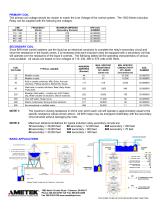
PRIMARY COIL The primary coil voltage should be chosen to match the Line Voltage of the control system. The 1500 Series Induction Relay can be supplied with the following line voltages. NOTE 1: The maximum closing resistance in ohms over which each coil will operate is approximately equal to the specific resistance values shown above. All B/W relays may be energized indefinitely with the secondary circuit shorted without damaging the coils. Maximum distance limitations for typical induction relay secondary circuits are: 12 secondary = 36,000 feet 90 secondary = 12,000 feet 480 secondary...
Open the catalog to page 2All AMETEK Drexelbrook catalogs and technical brochures
 Multipoint II Series
2 Pages
 ClearLine Series
2 Pages
 7014 and 7010 Series
2 Pages
 Unifloat Level Sensors
9 Pages
 Universal IV ™ CM Model
8 Pages
 Model 375
4 Pages
 Model 575 Series
5 Pages
 Model 575P
4 Pages
 Model 675
5 Pages
 Dumpstar Series
2 Pages
 Plugged Chute Detector
4 Pages
 Universal II Series
2 Pages
 Level Mate III
4 Pages
 Model 575S
5 Pages
 Model SST Slim-Line
4 Pages
 Model SDT
4 Pages
 Total Tank Level System
6 Pages
 Drexelbrook Level Measurement
16 Pages
 DR6300 Series
17 Pages
 DR5200 Series
17 Pages
 DR7000 Series
4 Pages
 Z4-Series
6 Pages
 Universal IV Sales Brochure
10 Pages
 Coal and Fly Ash Solutions
6 Pages
 RXL Series, IntelliPoint
4 Pages


Archived catalogs
 401-400 Series
4 Pages
 Model DDMC
8 Pages
 Accessories Drexelcage
2 Pages
 Point Level
5 Pages
 DR7000
4 Pages
 CM3 Series Cut Monitor
4 Pages
 701X Series Data Sheet
2 Pages
 PNT Series, ThePoint
4 Pages
 Model SDT
4 Pages
 USonic™ Series
4 Pages


- Surge protector
- Digital I/O
- AMETEK level switch
- IO module
- AMETEK liquid level switch
- Level probe
- Liquid level sensor
- Analog I/O
- Switching relay
- Digital IO module
- Float level switch
- Analog level sensor
- Transceiver module
- AMETEK stainless steel level switch
- AMETEK level transmitter
- AMETEK liquid level transmitter
- Electromechanical relay
- Analog IO module
- Serial I/O
- Digital output level sensor