- Catalogs
- Ametek Calibration
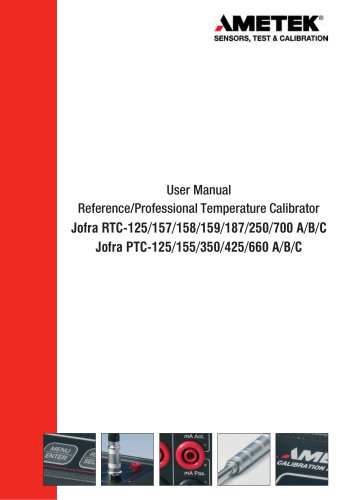
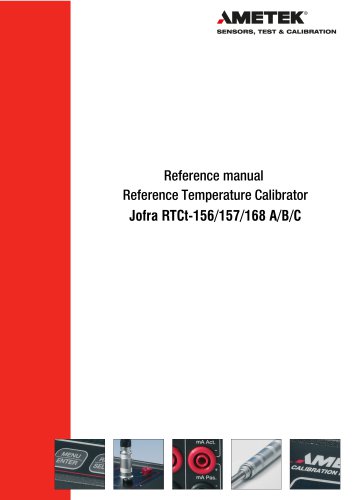
- ETC Temperature Calibrator User Manual
- Products
- Catalogs
- News & Trends
- Exhibitions
ETC Temperature Calibrator User Manual
1 /87Pages

ETC Temperature Calibrator User Manual
1 /87Pages
Catalog excerpts
VMETEK SENSORS, TEST & CALIBRATION Reference manual Temperature Calibrator
Open the catalog to page 1
User- and Reference manual Temperature Calibrator JOFRA ETC-125 A / 400 A / 400 R Copyright 2005 AMETEK Denmark A/S (123943-UK)
Open the catalog to page 2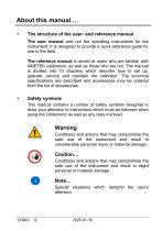
About this manual…. • The structure of the user- and reference manual The user manual sets out the operating instructions for the instrument. It is designed to provide a quick reference guide for use in the field. The reference manual is aimed at users who are familiar with AMETEK calibrators, as well as those who are not. The manual is divided into 10 chapters which describe how to set up, operate, service and maintain the calibrator. The technical specifications are described and accessories may be ordered from the list of accessories. Safety symbols This manual contains a number of safety...
Open the catalog to page 4
User manual Temperature Calibrator JOFRA ETC-125 A / 400 A / 400 R Copyright 2005 AMETEK DENMARK A/S (123943-UK)
Open the catalog to page 7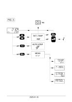
AUTO STEP
Open the catalog to page 11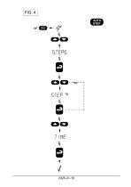
FIG. 4 AUTO STEP AUTO STEP
Open the catalog to page 12
ETC-calibrators are temperature calibrators designed to calibrate temperature sensors. Read this manual carefully before using the instrument and make sure that all safety instructions and warnings are observed.
Open the catalog to page 15
Read this manual carefully before using the instrument! In order to avoid any personal injuries and/or damage to the instrument all safety instructions and warnings must be observed. These calibrators contain Electrical and Electronic circuits and must be recycled or disposed of properly (in accordance with the WEEE Directive 2012/19/EU). • The calibrator must not be used for any purposes other than those described in this manual, as it might cause a hazard. • The calibrator has been designed for indoor use only and is not to be used in wet locations. • The calibrator is not to be used in hazardous...
Open the catalog to page 16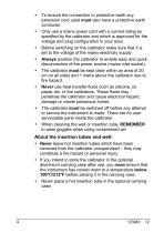
• To ensure the connection to protective earth any extension cord used must also have a protective earth conductor. • Only use a mains power cord with a current rating as specified by the calibrator and which is approved for the voltage and plug configuration in your area. • Before switching on the calibrator make sure that it is set to the voltage of the mains electricity supply. • Always position the calibrator to enable easy and quick disconnection of the power source (mains inlet socket). • The calibrator must be kept clear within an area of 20 cm on all sides and 1 metre above the calibrator...
Open the catalog to page 17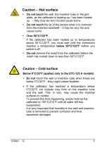
• Do not touch the well, the insertion tube or the grid plate, as the calibrator is heating up / has been heated up - they may be very hot and cause burns. • Do not touch the tip of the sensor when it is removed from the insertion tube/well - it may be very hot and cause burns. If the calibrator has been heated up to temperatures above 50°C/122°F, you must wait until the instrument reaches a temperature below 50°C/122°F before you switch it off. • Do not remove the insert from the calibrator before the insert has cooled down to less than 50°C/122°F. A Caution - Cold surface Below 0°C/32°F (applies...
Open the catalog to page 18
• Before cleaning the calibrator, you must switch it off, allow it to cool down and remove all cables. About the well, insertion tube and grid plate: • The well and the insertion tube must be clean before use. • Do not pour any form of liquids into the well. It might damage the well or cause a hazard. • Scratches and other damage to the insertion tubes should be avoided by storing the insertion tubes carefully when not in use. • The insertion tube must never be forced into the well. The well could be damaged as a result, and the insertion tube may get stuck. • The insertion tube must always be...
Open the catalog to page 19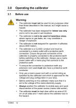
Warning • The calibrator must not be used for any purposes other than those described in this manual, as it might cause a hazard. • The calibrator has been designed for indoor use only and is not to be used in wet locations. • The calibrator is not to be used in hazardous areas, where vapour or gas leaks, etc. may constitute a danger of explosion. • The calibrator is not designed for operation in altitudes above 2000 meters. • The calibrator is a CLASS I product and must be connected to a mains outlet with a protective earth connection. Ensure the ground connection of the calibrator is properly...
Open the catalog to page 20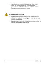
• Never use heat transfer fluids such as silicone, oil, paste, etc. in the calibrators. These fluids may penetrate the calibrator and cause electrical hazard, damage or create poisonous fumes. • Do not touch the grid plate, the well or the insertion tube as the calibrator is heating up - they may be very hot and cause burns. • Do not touch the handle of the calibrator during use - it may be very hot and cause burns.
Open the catalog to page 21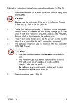
Follow the instructions below before using the calibrator (cf. Fig. 1): Place the calibrator on an even horizontal surface away from all draughts. Do not use the instrument if the fan is out of order. Ensure a free supply of air to the fan (pos. 5). 2. Check that the voltage shown on the label above the power control switch is identical to the mains voltage (ETC-400 only). If not, the instrument should be returned to AMETEK Denmark A/S or the distributor for replacement. 3. Plug in the cable below (pos. 3) the power control switch (pos. 4) and check that the earth connection is present. 4. The...
Open the catalog to page 22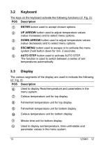
The keys on the keyboard activate the following functions (cf. Fig. 2): POS Description ENTER button used to accept chosen options. DOWN ARROW button used to adjust temperature values (value decreases) and to select menu options. ESC/MENU button used to escape or to activate the menu system (hold button down for min. 2 seconds). AUTO STEP button used to activate AUTO STEP. The function is used to switch between a series of settemperatures automatically. UP ARROW button used to adjust temperature values (value increases) and to select menu options. The various segments of the display are used...
Open the catalog to page 23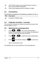
@ AUTO STEP symbol used to indicate that the function is active (symbol flashes repeatedly). @ Check mark displayed when the calibrator is stable. The instrument is designed for the following connections (cf. Fig. 1): The instrument’s functions are divided into hierarchical groups. See the key diagram in Fig. 3. ^ Press or . The current set-temperature flashes (the starting point is the last chosen set-temperature even if the instrument has been turned off). ^ Press or to select the required temperature. Press to accept the change or {MEN^ to cancel and return to the previous value. The calibrator...
Open the catalog to page 24All Ametek Calibration catalogs and technical brochures
 Type T Deadweight Tester
8 Pages
 ATMi Temperature Module
7 Pages
 XP2i Data Recorder
6 Pages
 Temperature Pressure Process
12 Pages
 AMETEK Calibration Brochure
12 Pages
 Maritime Brochure
8 Pages
 CPF Brochure (D)
4 Pages
 APM Advanced Pressure Module
6 Pages
 Product Overview Brochure
8 Pages
 GaugeCalHP Manual
20 Pages
 24 VDC Power Supply Manual
7 Pages
 24 VDC Power Supply
4 Pages
 FastCalXP
9 Pages


- Management software solution
- Automation software solution
- Data logger
- AMETEK resistance temperature sensor
- Process software
- AMETEK pressure gauge
- AMETEK Windows software
- Real-time software
- Cloud-based software
- Control software
- Digital indicator
- Analog pressure gauge
- Industrial software
- Interface software
- AMETEK measurement software
- Pt100 temperature transducer
- AMETEK thermocouple
- Data-logger with screen