- Catalogs
- Ametek Calibration
- DTI-1000 Temperature Indicator Reference Manual
- Products
- Catalogs
- News & Trends
- Exhibitions
DTI-1000 Temperature Indicator Reference Manual
1 /46Pages
DTI-1000 Temperature Indicator Reference Manual
1 /46Pages
Catalog excerpts
VMETEK SENSORS, TEST & CALIBRATION Reference manual Digital Temperatur Indicator
Open the catalog to page 1
Reference Manual Digital Temperature Indicator JOFRA DTI-1000 A/B Copyright 2005 AMETEK Denmark A/S
Open the catalog to page 2
This reference manual is aimed at users who are familiar with AMETEK calibrators, as well as those who are not. The manual is divided into 8 chapters, which describe how to set up, operate, service and maintain the indicator. The technical specifications are described as well. This manual contains a number of safety symbols designed to draw your attention to instructions which must be followed when using the instrument, as well as any risks involved. Warning Conditions and actions which may compromise the safe use of the instrument and result in considerable personal injury or material damage....
Open the catalog to page 3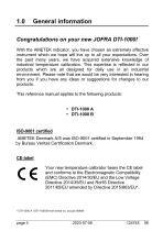
With the AMETEK indicator, you have chosen an extremely effective instrument which we hope will live up to all your expectations. Over the past many years, we have acquired extensive knowledge of industrial temperature calibration. This expertise is reflected in our products which are all designed for daily use in an industrial environment. Please note that we would be very interested in hearing from you if you have any ideas or suggestions for changes to our products. This reference manual applies to the following products: AMETEK Denmark A/S was ISO-9001 certified in September 1994 by Bureau...
Open the catalog to page 5
Technical assistance Please contact the dealer from whom you acquired the instrument if you require technical assistance. This instrument is warranted against defects in workmanship, material and design for two (2) years from date of delivery to the extent that AMETEK will, at its sole option, repair or replace the instrument or any part thereof which is defective, provided, however, that this warranty shall not apply to instruments subjected to tampering or, abuse, or exposed to highly corrosive conditions. THIS WARRANTY IS IN LIEU OF ALL OTHER WARRANTIES WHETHER EXPRESS OR IMPLIED AND AMETEK...
Open the catalog to page 6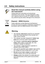
Read this manual carefully before using the instrument! Please follow the instructions and procedures described in this manual. They are designed to allow you to get the most out of your DTI system and avoid any personal injuries and/or damage to the instrument. These calibrators contain Electrical and Electronic circuits and must be recycled or disposed of properly (in accordance with the WEEE Directive 2012/19/EU). • The indicator must not be used for any purposes other than those described in this manual, as it might cause a hazard. • The indicator has been designed for indoor use only and...
Open the catalog to page 7
Caution… When connecting the PC and the indicator please ensure that both the PC and the indicator are switched off at the mains. Failure to do so may result in your equipment being damaged.
Open the catalog to page 8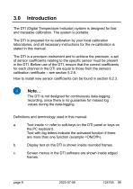
The DTI (Digital Temperature Indicator) system is designed for fast and traceable calibration. The system is portable. The DTI is prepared for re-calibration by your local calibration laboratories, and all necessary instructions for the re-calibration is stated in this manual. The DTI is a precision instrument and to achieve the precision, a set of sensor coefficients relating to the specific sensor must be present in the DTI. Before use of the DTI, ensure that the correct coefficients for each channel in the DTI are equal to those from the sensors calibration certificate - see section 5.2.6....
Open the catalog to page 9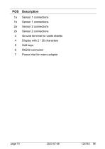
3 Ground terminal for cable shields 4 Display with 2 * 20 characters 7 Power inlet for mains adapter
Open the catalog to page 11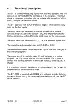
Functional description The DTI is used for measuring inputs from two RTD sensors. The two sensors are connected to the connectors in the top plate. The input signal is compared to the two internal resistor references from which the input signal can be determined. The DTI operates with a 2*20 character display, which continuously read out the two inputs. The input value can be shown as the actual read value for both sensors, the peak values for sensor 1 or 2, the differential value for the two sensors or as the differential peak value for the two sensors. The input value can be shown in Ω, °C,...
Open the catalog to page 12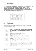
The DTI only uses the display for all indications. The display has 2*20 characters which will swap between read-out values or menu selection when requested. Please see section 5.2.1 to 5.2.7 for possible display read-outs. Please note that the error messages will also be showed in the display, see section 7.3. CALIBRATION INSTRUMENTS MENU ENTER RESET SELECT There are 4 soft-keys on the touch pad panel, where 2 of the softkeys have a double function. MENU ENTER RESET SELECT Switch ON or switch OFF the DTI. Please press down the key at least 0.2 seconds in order to switch on the unit. MENU toggles...
Open the catalog to page 13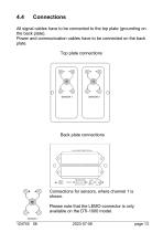
All signal cables have to be connected to the top plate (grounding on the back plate). Power and communication cables have to be connected on the back plate. Top plate connections Back plate connections Connections for sensors, where channel 1 is shown. Please note that the LEMO-connector is only available on the DTI-1000 model. SENSOR 1
Open the catalog to page 14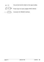
Ground terminal for shield on the signal cables. Power input for mains adapter 9VDC 200mA.
Open the catalog to page 15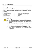
Both of the DTI models are intended for use in areas which meet the following: Warning • The indicator must not be used for any purposes other than those described in this manual, as it might cause a hazard. • The indicator has been designed for indoor use only and is not to be used in wet locations. • The indicator is not to be used in hazardous areas, where vapour or gas leaks, etc. may constitute a danger of explosion.
Open the catalog to page 16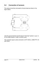
The sensor should be connected to the terminals as shown in the figure below: Use the ground terminal (see the figure "Overview" section 4, pos. 3) for the cable shields in order to reduce noise. The connector type to extra connector on DTI-1000 is: LEMO FFA 1S 304 CNAC.
Open the catalog to page 17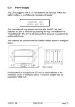
Power supply The DTI is supplied with 8 1.5 Volt batteries as standard. When the battery voltage is low following message will appear: BATTERY LOW PRESS ANY KEY This message will only appear one time after the DTI has been switched on, and is removed by pressing the key or . The DTI is still able perform accurate measurements a little while longer. The batteries are placed in the two battery holders shown in the figure below: 2 x 4 PCS BATTERIES TYPE AA Mains adapter It is also possible to supply the DTI from a mains adapter at the connector shown in the figure above. The mains adapter can be...
Open the catalog to page 18All Ametek Calibration catalogs and technical brochures
 Type T Deadweight Tester
8 Pages
 ATMi Temperature Module
7 Pages
 XP2i Data Recorder
6 Pages
 Temperature Pressure Process
12 Pages
 AMETEK Calibration Brochure
12 Pages
 Maritime Brochure
8 Pages
 CPF Brochure (D)
4 Pages
 APM Advanced Pressure Module
6 Pages
 Product Overview Brochure
8 Pages
 GaugeCalHP Manual
20 Pages
 24 VDC Power Supply Manual
7 Pages
 24 VDC Power Supply
4 Pages
 FastCalXP
9 Pages


- AMETEK temperature sensor
- Management software solution
- Automation software solution
- Data logger
- AMETEK resistance temperature sensor
- Process software
- AMETEK pressure gauge
- AMETEK Windows software
- Real-time software
- Cloud-based software
- Control software
- Digital indicator
- Analog pressure gauge
- Industrial software
- Interface software
- AMETEK measurement software
- Pt100 temperature transducer
- AMETEK thermocouple
- Data-logger with screen