- Catalogs
- Ametek Calibration
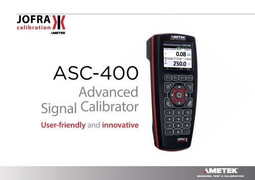
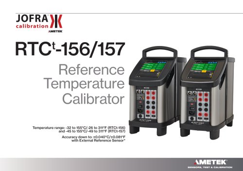
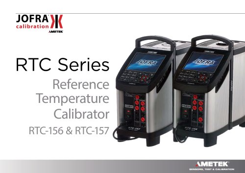
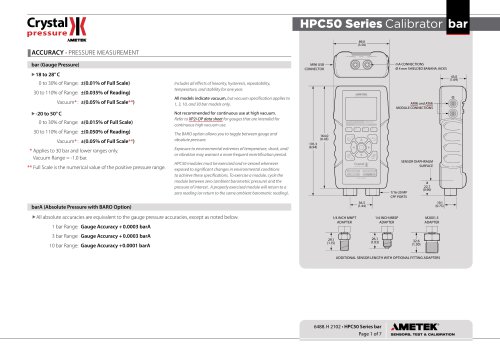
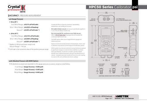
- ASC-400 Multifunction Process Calibrator Reference Calibrator
- Products
- Catalogs
- News & Trends
- Exhibitions
ASC-400 Multifunction Process Calibrator Reference Calibrator
1 /73Pages

ASC-400 Multifunction Process Calibrator Reference Calibrator
1 /73Pages
Catalog excerpts
Reference Manual Advanced Signal Calibrator Jofra ASC-400
Open the catalog to page 1
Reference Manual Advanced Signal Calibrator JOFRA ASC-400 Copyright 2014 AMETEK Denmark A/S
Open the catalog to page 2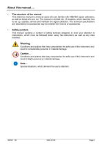
About this manual…. • The structure of the manual This reference manual is aimed at users who are familiar with AMETEK signal calibrators, as well as those who are not. The manual is divided into 12 chapters, which describe how to set up, operate, service and maintain the signal calibrator. The technical specifications are described and accessories may be ordered from the list of accessories. Safety symbols This manual contains a number of safety symbols designed to draw your attention to instructions, which must be followed when using the instrument, as well as any risks involved. Warning Conditions...
Open the catalog to page 3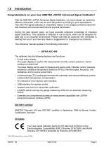
Congratulations on your new AMETEK JOFRA Advanced Signal Calibrator! With the AMETEK JOFRA Advanced Signal Calibrator, you have chosen an extremely effective instrument, which we are sure will perform according to your expectations. This ASC-400 signal calibrator is a handheld, battery or DC adaptor powered instrument that measures and sources electrical and physical parameters. During the past several years, we have acquired extensive knowledge of industrial signal calibration. This expertise is reflected in our products, which are all designed for daily use in an industrial environment. Please...
Open the catalog to page 6
Please contact the dealer from whom you acquired the instrument if you require technical assistance. This instrument is warranted against defects in workmanship, material and design for two (2) years from date of delivery to the extent that AMEtEk will, at its sole option, repair or replace the instrument or any part thereof which is defective, provided, however, that this warranty shall not apply to instruments subjected to tampering or, abuse, or exposed to highly corrosive conditions. THIS WARRANTY IS IN LIEU OF ALL OTHER WARRANTIES WHETHER EXPRESS OR IMPLIED AND AMETEK HEREBY DISCLAIMS ALL...
Open the catalog to page 7
Read this manual carefully before using the instrument! Please follow the instructions and procedures described in this manual. They are aimed at allowing you to make the best of your signal calibrator and avoid any personal injuries and/or damage to the instrument. /v-0\ The signal calibrator contains Electrical and Electronic circuits and must be properly recycled or disposed of (in accordance with the WEEE Directive 2012/19/EU). The signal calibrator is designed to calibrate and measure low voltage process signals. To ensure the safety of the operator and the instrument, DO NOT connect the...
Open the catalog to page 9
To avoid possible damage to the signal calibrator or to the equipment under test: • Disconnect the power and discharge all high-voltage capacitors before testing resistance or continuity. • Use the proper jacks, function, and range for your measurement or sourcing application. • If the message changes to "OL" the range limit is exceeded and the pressure source must immediately be removed from the APM to prevent damage to the pressure transducer inside. • To avoid damaging the pressure module from overpressure, never apply pressure above the rated maximum printed on the module. • To avoid damaging...
Open the catalog to page 10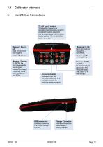
Calibrator Interface Input/Output Connections TC mV input / output Terminal for measuring or simulating thermocouples and mV. Accepts miniature polarized thermocouple plugs with flat in-line blades spaced 7.9 mm (0.312 in) center to center. Measure / Source mA Input terminals for sourcing and measuring current. Measure / V mA Input terminals for measuring , switch test, current, voltage and supplying Measure / Source V, Ω/RTD, Hz Input terminals for sourcing and measuring voltage, frequency, pulse train, resistance and RTDs. Measure Ω/RTD, 4w, 3/4w Input terminals for performing RTD measurements...
Open the catalog to page 11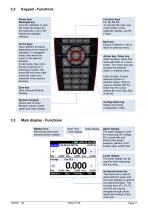
Keypad - Functions Power key/ Backlight key Turn the calibrator on and off. Press the button for five seconds to turn it off. Adjust the backlight intensity. Function keys F1, F2, F3, F4 To operate the menu bar at the bottom of the calibrator display, use the F-keys. Arrow Keys Have different functions depending on the mode of operation. In navigation mode, they move the cursor in the desired direction. In edit mode, they roll in the list of options or if entering a number, the arrow left and arrow right move the cursor one character in the desired direction. Zero key Zero Pressure Module reading....
Open the catalog to page 12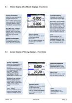
Upper display (Read-back display) - Functions Primary Parameters Determine what parameter is going to be measured. Backlight Intensity Indicates Low, Medium or High intensity on backlight The available options for the upper display are: CURRENT, VOLTAGE, SWITCH TEST, PRESSURE and LEAK TEST. Min./Max./Avg. readings Minimum, maximum and average value for the upper display reading. Visible when activated in the settings menu. Additional parameters Selection and selection of parameters relevant to the choice of primary parameter Secondary upper display Shows where in the preset span the measured...
Open the catalog to page 13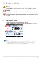
Operating the calibrator Warning Please inspect the Safety Instructions in section 2.0 before using the instrument. Caution… Please inspect the Safety Instructions in section 2.0 before using the instrument. Connect USB cable and APM before switching on the instrument, or before applying DC power. Basic operation (Setup) 1. Select mode for upper and lower display (RED markers). 2. Select the related options and functions for the selected modes (BLUE markers) Note… the light blue fields; they indicate a parameter / function that can be selected or altered in edit mode. This works like a build...
Open the catalog to page 14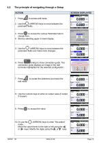
4.2 The principle of navigating through a Setup SCREEN DISPLAYED 1. Press to access edit mode. 2. Use the$^$ (ARROW) keys to move between the parameter fields. 3. Press to access the various Parameter lists to choose from. 4. Start by selecting upper or lower display. 5. Use the ^ (ARROW) keys to move between the parameter fields and make more changes... 6. Press (Help) to show connection guide. The connection guide displays an image of the rear terminals highlighted for the selected configuration. 7. Press dsl to accept the selections and leave the edit mode. 0.000 0.000 8. Use the numeric keys...
Open the catalog to page 15All Ametek Calibration catalogs and technical brochures
 Type T Deadweight Tester
8 Pages
 ATMi Temperature Module
7 Pages
 XP2i Data Recorder
6 Pages
 Temperature Pressure Process
12 Pages
 AMETEK Calibration Brochure
12 Pages
 Maritime Brochure
8 Pages
 CPF Brochure (D)
4 Pages
 APM Advanced Pressure Module
6 Pages
 Product Overview Brochure
8 Pages
 GaugeCalHP Manual
20 Pages
 24 VDC Power Supply Manual
7 Pages
 24 VDC Power Supply
4 Pages
 FastCalXP
9 Pages


- AMETEK temperature sensor
- Management software solution
- Automation software solution
- Data logger
- AMETEK resistance temperature sensor
- Process software
- AMETEK pressure gauge
- AMETEK Windows software
- Real-time software
- Cloud-based software
- Control software
- Digital indicator
- Analog pressure gauge
- Industrial software
- Interface software
- AMETEK measurement software
- Pt100 temperature transducer
- Data-logger with screen