
- Catalogs
- American Flow Control
- AMERICAN Restrained Joint Pipe

AMERICAN Restrained Joint Pipe

AMERICAN Restrained Joint Pipe
The document provides an overview of the standards and specifications for AMERICAN Restrained Joint Pipe and Fittings, referencing ANSI/AWWA standards. It highlights the need for restraining forces due to internal pressure in piping installations, typically achieved through concrete reaction blocking. For situations where this is impractical, AMERICAN offers restrained joint solutions for pipe sizes ranging from 4” to 64”.
The document lists various joints that provide restraint, including Flex-Ring®, Field Flex-Ring®, Fast-Grip®, Lok-Ring®, and MJ Coupled Joints. It also mentions joints not primarily furnished for restraint, such as Flange, Grooved, Flex-Lok, and Shouldered Joints.
The Fast-Grip® gasket is highlighted as a superior method for restraining ductile iron pipes and fittings, using a wedging action with high-strength stainless steel elements. It is suitable for working pressures of 350 psi for 4”-18” pipes and 250 psi for 20” and 24” sizes, allowing for specific deflection angles depending on the pipe size.
The assembly process for Fast-Grip® gaskets involves cleaning the socket and spigot, placing the gasket correctly, lubricating the joint, and ensuring proper alignment and deflection during assembly. Detailed steps and considerations for assembling and disassembling these joints are provided.
Allowable joint deflection angles are specified for different pipe sizes, with instructions for preparing field-cut pipes. The document advises on the use of assembly marks and proper beveling to ensure successful joint assembly.
Instructions for disassembling Fast-Grip® gasket joints are provided, including the use of disassembly kits. The document also discusses joint extension after installation, highlighting the flexibility and movement allowed by the Fast-Grip® gasket mechanism.
The Flex-Ring® joint pipe is described as a flexible, boltless restrained joint suitable for various applications, including trenchless installations. It is designed for working pressures up to 350 psi for sizes 4”-24” and 250 psi for sizes 30” and 48”.
The Flex-Ring Joint is available in sizes ranging from 4” to 48”. For sizes 4”-12”, the joint is UL listed and FM approved. The joint components include a gasket and a single ring, eliminating the need for loose lugs or heavy wedges.
The assembly involves inserting the plain end of the pipe into the Flex-Ring bell, followed by the insertion of the split flex-ring into the socket locking groove. Step-by-step instructions for both field assembly and disassembly of the Flex-Ring Joint are provided.
The fittings for 16”-48” Flex-Ring pipe meet ANSI/AWWA standards. The pipe is typically furnished with a standard asphaltic coating and cement lining, with special coatings available upon request.
The Flex-Ring Joint allows for safe deflection post-assembly, facilitating installation and accommodating settlement. Tables detail working pressures, allowable pulling loads, and deflection capabilities for various pipe sizes.
For field closures, the Fast-Grip® gasket is recommended for sizes 4”-30”. The document advises on joint extension after installation to enhance thrust-resisting forces and accommodate thermal expansion and contraction.
The document references ANSI/AWWA standards for the installation of ductile iron water mains. It emphasizes the importance of filling and testing restrained sections of pipelines after backfilling.
- Joint Extension: Necessary in applications where axial or lateral movement is undesirable.
- Disassembly Instructions: Flex-Ring joints can be disassembled using sharp wedges and disassembly shims.
- Field Flex-Ring Assembly: Involves cleaning, gasket insertion, spigot marking, and lubrication.
For vertical applications, standard Flex-Ring joints with weld beads are recommended. In underground installations, joint take-up is advantageous for generating increased thrust-resisting forces.
- Spigot Assembly Stripe Location: Provides specific measurements for the location of stripes from the spigot end for different pipe sizes.
- Recommended Spigot Diameters: Lists minimum and maximum diameters and circumferences for pipe field-cut locations.
The document highlights the importance of proper assembly and disassembly techniques to ensure the integrity and functionality of the pipeline system.
The document discusses the AMERICAN Lok-Ring® Joint Pipe, designed for water, sewage, or other liquids. It is manufactured in accordance with AWWA standards and is available in sizes 54" to 64".
Detailed disassembly instructions for Flex-Ring joints containing Field Flex-Rings are provided.
The Lok-Ring joint utilizes the sealing features of the AMERICAN Fastite Joint and complies with ANSI/AWWA standards.
For installations where axial or lateral movement is undesirable, special design or installation provisions may be necessary.
Tables provide dimensions and specifications for the Lok-Ring joint, including working pressure and allowable joint deflection.
The document covers the MJ Coupled Joint, offering joint restraint with a standard Mechanical Joint socket.
The document discusses the use of alloy steel for studs, tee-head bolts, nuts, and retaining rings.
Assembly instructions for the Mechanical Joint (MJ) are provided, ensuring straight alignment.
Tables list dimensions for MJ Coupled Joints, including outside diameter and socket depth.
Thrust collars are used to restrain pipelines by providing anchorage and support against soil.
Procedures for field welding ductile iron pipe joints are outlined, emphasizing safety precautions.
Welds should be applied using a D.C. arc welder with specific electrodes or wire.
The document advises on the use of thrust collars and coupling gland ends for restraining across couplings.
Guidelines for ensuring weld quality and safety are provided.
Details on various joint types, including MJ Coupled Joint, Flex-Ring® Joint, and Lok-Ring® Joint, are provided.
For Flex-Ring Joint sizes 14”-48”, contact AMERICAN for field welding applications.
Instructions for pull-extending restrained joints to remove slack are provided.
AMERICAN manufactures ductile iron pipes and fittings in accordance with AWWA standards, with specific warranty information provided.
AMERICAN reserves the right to modify designs, materials, specifications, or dimensions without prior notice.
Catalog excerpts

Joint Pipe
Open the catalog to page 1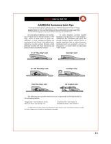
AMERICAN Restrained Joint Pipe The principal standards relating to applicable features of AMERICAN Restrained Joint Pipe and Fittings are ANSI/AWWA C151/A21.51, ANSI/AWWA C110/A21.10, ANSI/AWWA C111/A21.11 and ANSI/ AWWA C153/A21.53. These and other standards are referenced throughout this Section either by the full ANSI/AWWA designation or by only the AWWA numbering, such as AWWA C151. In many piping installations, the restraining of forces due to internal pressure at fittings, valves, or dead ends is a major consideration. In most underground piping, the restraining of such forces is normally...
Open the catalog to page 2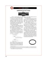
AMERICAN Fast-Grip® Gasket American Fast-Grip gaskets have been proven to be a superior field-adaptable method of restraining 4”-30” ductile iron pipe or fittings. The restraint provided by the patented* AMERICAN Fast-Grip® gasket is due to the development of wedging action between pairs of high-strength stainless steel elements spaced around the gasket. The outer metal element acts as a bearing member for the wedge-shaped inner element which has sharp teeth on its inner surface for gripping the spigot. Because of the wedging design utilized, the force between the spigot and the socket of the...
Open the catalog to page 3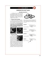
AMERICAN Fast-Grip® Gasket Assembly Instructions Assembling pipe and fitting joints using Fast-Grip gaskets is simple. It is very similar to the assembly of Fastite joints shown in Section 2. Fast-Grip gaskets may be used in lieu of standard Fastite gaskets in the bells of Fastite and FlexRing joint pipe and fittings where easy, fieldadaptable restraint is desired. 1. Cleaning of Socket and Spigot Clean the socket and plain end thoroughly, removing any mud, sand, gravel, ice, frozen material, or other matter that could prevent a proper joint seal. Material in the gasket grooves may cause the...
Open the catalog to page 4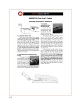
AMERICAN Fast-Grip® Gasket Assembly Instructions—Continued 3. Lubrication of the Joint With a clean brush, apply a liberal amount of regular Fastite lubricant completely over the end of the pipe, the spigot radius, and the outer surface of the pipe up to the assembly stripe. Also apply lubricant completely over the exposed inner surface of the gasket. AMERICAN supplies an extra 10% of lubricant to be used with the Fast-Grip joints to ensure ease of assembly. Use only lubricant provided by AMERICAN. For underwater conditions, special AMERICAN underwater lubricant is recommended and is available...
Open the catalog to page 5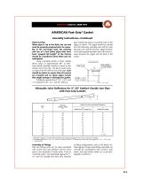
AMERICAN Fast-Grip® Gasket Assembly Instructions—Continued Field-Cut Pipe When pipe is cut in the field, the cut end must be properly prepared prior to assembly. In 18” and larger sizes, the ordering and use of a few select pipes that have been “gauged full length” at the factory should be considered when field cuts are anticipated. Using a portable grinder or other suitable device, place an approximately 3⁄8”- to 5⁄8”long smooth assembly chamfer or bevel on the outside end of the pipe. This bevel should make an angle of 30-40° with the axis of the pipe. Care should be taken to ensure that all...
Open the catalog to page 6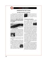
AMERICAN Fast-Grip® Gasket Assembly Instructions—Continued Fast-Grip gasketed joints requiring a particular orientation (such as with bends) should be assembled in the intended service position. In some instances, this may be accomplished more easily by first assembling the bend on a pipe above the trench. The jointed bend and pipe may then be lowered (orienting as required) and assembled into place. Relative rotation of joint members to one another after assembly is not recommended as it could cause damage or leakage. See Push-On Fittings Assembly Instructions in Section 4. Disassembly Instructions...
Open the catalog to page 7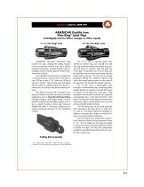
AMERICAN Ductile Iron Flex-Ring® Joint Pipe Centrifugally Cast for Water, Sewage, or Other Liquids 4”-12” Flex-Ring® Joint AMERICAN Flex-Ring® Restrained Joint Ductile Iron pipe, utilizing the sealing features of the time-proven Fastite® Joint and a boltless restrained connection, provides flexible, easily assembled, positive restraint against endwise separation due to thrust. The patented1 Flex-Ring Joint is designed for a working pressure2 equal to that of the pipe or up to 350 psi in sizes 4”-24” and up to 250 psi in sizes 30” and 48”. The joint has been thoroughly factory tested to withstand...
Open the catalog to page 8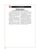
AMERICAN Ductile Iron Flex-Ring® Joint Pipe Centrifugally Cast for Water, Sewage, or Other Liquids No loose lugs, heavy wedges, rubber tubes, etc. are necessary. Also, there is no need to orient bells to ensure proper installation, though for convenience, most installers orient the split locking ring ends in 4”-12” sizes away from the very bottom of the joints. Just follow the simple instructions shown on the following pages, and positive restraint is ensured. Flex-Rings, Flex-Ring segments, and retainer rings are manufactured of ductile iron compatible with pipe. Welds and weld beads (if used)...
Open the catalog to page 9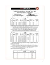
AMERICAN Ductile Iron Flex-Ring® Joint Pipe Standard Dimensions and Pressure Ratings 14”-48” Nominal Laying Length** ft. B F Allowable A Pulling O.D. Socket Bell Load in. Depth O.D.† in. in. lb.†† Allowable Deflection degree Empty Pipe Buoyancy in Water (lb/ft)^^ –5 –2 * Working pressure is the maximum pressure rating of the joint and is based on its capability to resist thrust due to internal pressure. If higher working pressure is required, check AMERICAN. ** Laying length is nominal 20’. Where exact lengths are required, contact AMERICAN. Minimum laying lengths for Flex–Ring & Flex–Ring End...
Open the catalog to page 10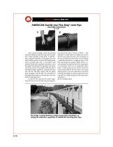
AMERICAN Ductile Iron Flex-Ring® Joint Pipe Assembly Instructions 4”-12” Prior to joint assembly, remove the packing material holding the split flex-ring onto the pipe. (See “Field Assembly of Flex-Ring” if split flexring is shipped separately.) Thoroughly clean the socket locking groove as well as the Fastite gasket recess and pipe plain end. In accordance with standard Fastite joint assembly instructions, insert the gasket and lubricate the pipe plain end, bevel, and inside surface of the gasket. With the pipe in essentially straight alignment, assemble the plain end into the Flex-Ring socket...
Open the catalog to page 11All American Flow Control catalogs and technical brochures
 4"-24" Tapping Sleeves
8 Pages
 Swing Check Valves Sales
20 Pages
 Material Safety Data Sheet
2 Pages
 AMERICAN Pipe Joints
27 Pages


