

nx3a1x-nexus

nx3a1x-nexus
The AMCI Nexus NX3A1X is a networked resolver programmable limit switch (PLS) module designed for high-speed packaging and assembly machines. It supports multiple networks such as ControlNet, DeviceNet, Ethernet, Profibus, and Modbus TCP/IP. The module uses a brushless resolver transducer for position feedback and can generate up to 16 limit switch outputs based on position and velocity.
The module operates in Independent Mode, where each output functions independently, and Group Mode, which combines outputs into up to six groups with specific operating modes.
The module has 16 I/O points, with eight outputs and all inputs located on the module. Additional outputs can be connected via an external relay board. Inputs can be programmed as high or low true and are divided into two groups of eight, functioning as either sinking or sourcing inputs.
The module includes non-volatile memory for saving setup data and On/Off setpoints. It supports programmable parameters such as transducer fault latch, scale factor, and limit switch type.
The module requires a power supply of 10 to 30Vdc, with a recommended range of 18 to 30Vdc. It features a resolver status LED indicating operational status and fault conditions. Dimensions are 10 inches in length, 4 inches in width, and 4.75 inches in height.
The module uses a CTL-(x) cable for connecting to AMCI single resolver transducers and is compatible with various AMCI transducers. It can be mounted on a DIN rail or panel.
Operating temperature ranges from 0 to 60°C, with a storage temperature of -40 to 85°C. The module operates with a typical throughput time of 100µs.
AMCI provides an 18-month warranty for defects under normal use. Technical support is available 24/7 via phone and online resources.
The document details specifications for the NX3A1X Networked Resolver PLS Module, including relay board connections. An additional RB-8 relay board can be connected if more than the eight built-in outputs are required. Connections are made using CRP-(x) cables, which are shielded and come in various lengths.
The NX3A1X module is programmed through output registers and has several programmable parameters, including module operation, setup, transducer setup, limit switch, and group setup parameters.
The module allows for output state control without network connection, increment/decrement of limit switch setpoints, and force control of outputs and inputs. The tachometer response can be set to update every 120 mSec or 504 mSec.
Transducer setup includes applying presets, setting count direction, and handling transducer faults. Limit switch parameters include types, motion ANDing, enable ANDing, and ON/OFF setpoints.
Two parameters allow the limit switch channel to compensate for fixed delays in the system, with a maximum compensation of ±99.9 mSec.
When using Group Mode, Group Setup Parameters must be programmed. A maximum of six groups is available, with outputs assigned consecutively.
Seven modes define group operations, ranging from simple limit switch operation to complex synchronization with product detection and handling machine stops.
Each group has an internal limit switch used to enable or disable inputs and outputs, depending on the operating mode.
Adjusts machine position for the group, acting as a position offset or preset depending on the mode.
Use Independent Mode for resolver position-based limit switches without Group Mode complexity.
Use Group Mode to control multiple outputs from a single input, with various modes for different operational needs.
The module communicates resolver position, velocity data, module status, and programming errors to the PLC using 20 sixteen-bit input registers.
The module is programmed through 40 sixteen-bit output registers, organized into five programming blocks to manage data efficiently.
Used to select the programming block to be sent to the NX3A1X, with specific bits controlling various functions.
This document provides detailed specifications and programming instructions for the NX3A1X Networked Resolver PLS Module.
The output programming block consists of words 1 to 39, where specific words control the programming of outputs.
This block allows for the adjustment of setpoints, with specific control bits for changing on/off setpoints.
The force function allows immediate changes to outputs without a programming cycle.
The module connects to ControlNet via BNC connectors and uses rotary switches for node address selection.
The module features four status LEDs indicating network and module status.
The document concludes with a brief overview of the DeviceNet connector, detailing pin functions and standard wire colors.
The NX3A1X Networked Resolver PLS Module uses DIP switches for setting the node address and baud rate.
The module includes four network status LEDs indicating various states such as power status, operational status, and fault conditions.
The minimum network update time for the NX3A1D is 5ms.
To add the NX3A1D to a network, it must be registered in the RSNetWorx for DeviceNet software using EDS files.
The NX3A1E module uses an IP address format of 192.168.000.XXX, configurable via DIP switches.
LEDs indicate network and module status, such as power, connection status, and errors.
The NX3A1P module uses a 9-pin D-sub connector for Profibus communication.
Instructions are provided for integrating the AMCI Nexus with the SST-PFB-SLC Profibus interface module.
The document outlines the specifications for the NX3A1X Networked Resolver PLS Module, focusing on its integration with Modbus TCP/IP networks.
Includes changing Modbus TCP/IP address and setup examples for network integration.
Recommends using a BootP server for IP configuration and provides detailed steps for setting up network connections.
Includes Modbus TCP/IP Ethernet Status LEDs and IP Address Selection methods.
The document has undergone several revisions, with the latest version 1.0 released on 7/14/06.
Catalog excerpts
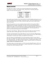
NX3A1X Specifications Rev 1.0 Networked Resolver PLS Module Module Overview This AMCI Nexus module is a single resolver input programmable limit switch module that communicates on a network. The available networks, along with the corresponding AMCI part numbers, are shown in the following table. Network ControlNet DeviceNet Ethernet Profibus Modbus TCP/IP Each module accepts a brushless resolver based transducer for position feedback and generates up to 16 limit switch outputs based on the transducers’ position and velocity. The NX3A1X module has several modes of operation that allow you to enable or disable the outputs based on discrete inputs and the speed of the machine. The NX3A1X module has two modes of operation, Independent Mode and Group Mode. While in Independent Mode, each output is independent of the others and has a corresponding input that is ANDed with the output. When in Group Mode, the outputs are combined into groups. The NX3A1X module has a maximum of six groups. Each group is assigned an Operating Mode that controls how the outputs fire. At this time, there are a total of seven Operating Modes. These Operating Modes are geared towards high speed packaging and assembly machines. This unit has sixteen I/O points. Eight of the outputs and all sixteen inputs are located on the Nexus module itself, and the remaining eight outputs can be located on an external relay board. The inputs can be programmed to be used either high true or low true, and provide ANDing functions and group control. The inputs are divided into two groups of eight, and can be used as either sinking or sourcing inputs. The status of the 16 inputs is also reported over the Network. Each of the outputs has 8 On/Off setpoints, and can be programmed to operate in normal, timed, or pulse mode. The outputs can be ANDed with an input or with a motion detector, and can also be forced ON or OFF from the PLC. The outputs will turn off when there is a transducer fault condition, even if it is a clearable transducer fault. The status of the 16 outputs is reported to the PLC over The Network. Outputs should not be programmed on the fly. The module contains a non-volatile memory so all of the setup data and On/Off setpoints will be saved on power down. Because the non-volatile memory is a battery backed RAM, all of the parameters can be changed often without damaging the module. 20 Gear Drive, Plymouth Industrial Park, Terryville, CT 06786 Tel: (860) 585-1254 Fax: (860)584-1973 E-mail: sales @amci.com
Open the catalog to page 1
NX3A1X Specifications Rev 1.0 Networked Resolver PLS Module Table of Contents General Information Hardware Overview Chapter 1 Status LED Function Power Requirements Dimensions Resolver Wiring Mounting Specifications Input Functions Relay Board Connections Programmable Parameters Chapter 2 Module Operation Parameters Module Setup Parameters Transducer Setup Parameters Limit Switch Parameters Group Setup Parameters Independent Mode Operations Group Mode Operations Chapter 4 Group Inputs Group Modes Input Registers & Data Output Registers & Data Chapter 6 Setup Programming Block Group Programming...
Open the catalog to page 2
NX3A1X Specifications Rev 1.0 Networked Resolver PLS Module General Information Important User Information The products and application data described in this manual are useful in a wide variety of different applications. Therefore, the user and others responsible for applying these products described herein are responsible for determining the acceptability for each application. While efforts have been made to provide accurate information within this manual, AMCI assumes no responsibility for the application or the completeness of the information contained herein. Throughout this manual, the...
Open the catalog to page 3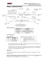
NX3A1X Specifications Rev 1.0 Networked Resolver PLS Module Chapter 1: Hardware Overview 8 Relay Outputs Input Connector Connection to additional Relay Board Input Status LEDs not used Network Status and Interface (See the Network installation guides at the end of the specifications) Resolver Status LED LED Pattern solid green flashing green flashing red solid red Function Resolver OK Clearable Transducer Fault Non Clearable Transducer Fault Module Fault Power Requirements Power Connector Pin Function 1 10 to 30Vdc 2 DC Common 3 Chassis Ground Note: The Chassis Ground Pin is connected to the...
Open the catalog to page 4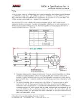
NX3A1X Specifications Rev 1.0 Networked Resolver PLS Module Wiring A CTL-(x) cable, where (x) is the length in feet, is used to connect an AMCI single resolver transducer to an NX3A1X module. If you order a CTL-(x) cable from AMCI that is less than 100 feet long, we ship a cable that is made from a Belden 9873 or equivalent. If you order a CTL-(x) cable that is over 100 feet, we ship a cable made from a Belden 9730 or equivalent. One end of the CTL-(x) has a Bendix MS connector that mates with all AMCI single resolver transducers that have a connector. The other end is pigtailed at the factory...
Open the catalog to page 5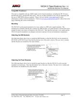
NX3A1X Specifications Rev 1.0 Networked Resolver PLS Module Compatible Transducers This unit is compatible with any AMCI single resolver based transducer, including the HT-20 series, the H25-XX series, and the HT-20-X series. The use of other transducers may also be supported with the use of AMCI RM reference modules. Please visit our website, www.amci.com for more information on these resolver transducers. Click on www.amci.com/resolvers.asp for a direct link to the page containing the resolver information. Mounting The NX3A1X can be panel mounted in two ways, either on a DIN rail or panel mounted....
Open the catalog to page 6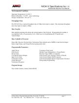
NX3A1X Specifications Rev 1.0 Networked Resolver PLS Module Environmental Conditions Operating Temperature: 0 to 60° C Relative Humidity: 5 to 95% (non-condensing) Storage Temperature: -40 to 85° C Throughput Time: The NX3A1X has a typical throughput time of 100µs from input to output. The maximum throughput time from input to output is 200µs. Data Transfer Data updated automatically during the normal update of the Network. Programming the module is accomplished with a Programming Cycle, which uses two handshaking bits (Transmit and Acknowledge). Data Available to Processor Status Bits, Resolver...
Open the catalog to page 7All AMCI catalogs and technical brochures
 nr25-ethernet-ip-encoder
2 Pages
 gen_epac-0g010
70 Pages
 AMCI Resolver Transducers
4 Pages
 AMCI Company Overview
6 Pages


- Electromotor
- DC electromotor
- Angular encoder
- Digital I/O
- Incremental encoder
- IO module
- 24 V motor
- Incremental rotary encoder
- Analog I/O
- Digital IO module
- Absolute rotary encoder
- Solid-shaft rotary encoder
- Stepper motor
- Permanent magnet motor
- Motor controller
- Analog IO module
- High-speed motor
- Single-turn rotary encoder
- Flange rotary encoder
- Stepper motor controller