CFC depuration plant
1 /9Pages

CFC depuration plant
1 /9Pages
Catalog excerpts

CFC DEPURATION PLANT APPLIED AT DISPOSAL REFRIGERATORS PROCESS TECHNICAL PRESENTATION Date: 13.11.2014 File name: DD14003AF Author: Andrea FORTUNA Pag 1 of 9 VENTILAZIONE INDUSTRIALE srl Via Adamello, 9 - 20851 Lissone (MB) – Italy - Tel. +39 039 24 56 105 / +39 039 483 498 Email: [email protected] - Web: www.amboso.com Reg. Soc. Trib. Monza 54794 – R.E.A. Milano N. 1444463 – C.F. e P.I. 02404270965
Open the catalog to page 1
INDEX 1- CFC ( chlorofluorocarbon ) 2- DISPOSAL REFRIGERATORS PROCESS 3- CFC DEPURATION PLANT 3.1- Process description 3.2- Devices description Pag 2 of 9 VENTILAZIONE INDUSTRIALE srl Via Adamello, 9 - 20851 Lissone (MB) – Italy - Tel. +39 039 24 56 105 / +39 039 483 498 Email: [email protected] - Web: www.amboso.com Reg. Soc. Trib. Monza 54794 – R.E.A. Milano N. 1444463 – C.F. e P.I. 02404270965
Open the catalog to page 2
1 - CFC ( chlorofluorocarbon ) A chlorofluorocarbon (CFC) is an organic compound that contains only carbon, chlorine, and fluorine, produced as a volatile derivative of methane, ethane, and propane. They are also commonly known by the DuPont brand name Freon. The most common representative is dichlorodifluoromethane (R-12 or Freon-12). Many CFCs have been widely used as refrigerants, propellants (in aerosol applications), and solvents. Because CFCs contribute to ozone depletion in the upper atmosphere, the manufacture of such compounds has been phased out under the Montreal Protocol, and they...
Open the catalog to page 3
2) Insulating foam shall not be manually removed; 3) The crushing of cabinets and the separation of crushed fractions shall be performed in a way so that emissions of VFCs and VHCs to the atmosphere are minimised according to national legislation; 4) The residual content of VFCs contained in the separated metal and plastics fractions shall be minimised; 5) The residual VFCs within the crushed insulating foam shall not be released to the atmosphere. They shall be converted into compounds that do not deplete the ozone layer; 6) The total mass of blowing agent (sum of VHCs and VFCs) removed from...
Open the catalog to page 4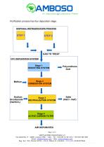
Purification process has four depuration stage. DISPOSAL REFRIGERATORS PROCESS GAS TO TREAT CFC DEPURATION SYSTEM Stage 1 DEDUSTING SYSTEM Polyurethane dust Stage 2 COMBUSTION SYSTEM Stage 3 NEUTRALIZATION SYSTEM Stage 4 ACTIVE CARBON FILTER AIR DEPURATED Pag 5 of 9 VENTILAZIONE INDUSTRIALE srl Via Adamello, 9 - 20851 Lissone (MB) – Italy - Tel. +39 039 24 56 105 / +39 039 483 498 Email: [email protected] - Web: www.amboso.com Reg. Soc. Trib. Monza 54794 – R.E.A. Milano N. 1444463 – C.F. e P.I. 02404270965
Open the catalog to page 5
Stage 1 Dedusting system, gas sucked from shredder have inside some dust (mainly polyuretan dust), before to treat this gas is important remove all dust. Stage 2 Combustion system, gas from stage 1 is completely oxidated inside a combustion chamber. Following is possible to see chemical oxidation reaction(1) inside combustion chamber: CCl2F2 + O2 + 2H2O => 2HCl + 2HF + CO2 From oxidation (combustion) reaction chloride acid ( HCl ) and hydrofluoric acid ( HF ) are formed. These compounds cannot be emitted into atmosphere, consequently gas with these compounds must be treated. (1): in the example...
Open the catalog to page 6
3.2 - Devices description Depuration system consists of four depuration stages in series, constituted respectively by: • bag filter as the first stage of reduction of dry powders of polyurethane derived from the shredding process; • regenerative combustion plant with three towers is the second stage to remove the volatile organic compounds; • gas/solid reactor and bag filter as third depuration stage, in this stage hydrochloric acid and hydrofluoric acid ( generated by CFC's combustion ) are removed with sodium bicarbonate; • the final depuration stage is a active carbon filter. FIRST FILTRATION...
Open the catalog to page 7
seconds, the direction of flow of gas in the combustion chamber is reversed so that the three ceramic beds exchange the function of preheating and recovery. The airflow always impinges two ceramic beds, while the third is on standby. The tower placed on stand-by contains polluted air so, to drain this tower is sucked enviromental air. This design allows achieving a continuity in the results of VOC removal, also when changing the valves. THIRD FILTRATION STAGE CFC's combustion generates hydrogen chloride and hydrogen fluoride, in order to purify these pollutions the gas is sent to an acid neutralization...
Open the catalog to page 8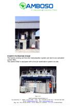
FOURTH FILTRATION STAGE The fumes coming out from the neutralization system are sent to an activated carbon filter. The carbon filter is equipped with a hot air reactivation system on-site. Pag 9 of 9 VENTILAZIONE INDUSTRIALE srl Via Adamello, 9 - 20851 Lissone (MB) – Italy - Tel. +39 039 24 56 105 / +39 039 483 498 Email: [email protected] - Web: www.amboso.com Reg. Soc. Trib. Monza 54794 – R.E.A. Milano N. 1444463 – C.F. e P.I. 02404270965
Open the catalog to page 9All AMBOSO catalogs and technical brochures
 Riconcentration Baia
2 Pages
 ReCol System
5 Pages


- Radial fan
- Solids separator
- Air circulation fan
- Industrial fan
- Extraction fan
- Industrial use filter
- Centrifugal classifier
- Particle separator
- Exhaust fan
- Air separator
- Stationary fume extractor
- Filter for chemical applications
- Dust fume extractor
- High-efficiency separator
- Cyclone classifier
- Rotary valve
- Dry separator
- Belt-driven fan
- Scrubber System