Catalog excerpts
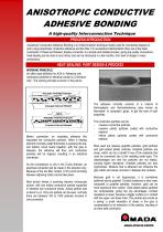
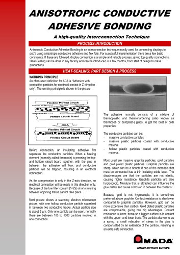
ANISOTROPIC CONDUCTIVE ADHESIVE BONDING A high-quality Interconnection Technique PROCESS INTRODUCTION Anisotropic Conductive Adhesive Bonding is an interconnection technique mostly used for connecting displays to pcb’s using anisotropic conductive adhesive and flex foils. For successful implementation there are a few basic constraints. If these are followed, display connection is a simple and reliable process, giving top quality connections. Heat-Sealing can be done in any factory and can be introduced in a few months, from start of design to mass productions. HEAT-SEALING: PART DESIGN & PROCESS WORKING PRINCIPLE An often-used definition for ACA is “Adhesive with conductive particles for electrical contact in Z-direction only”. The working principle is shown in the picture below. The adhesive normally consists of a mixture of thermoplastic and thermohardening (also known as thermoset- or duroplast-) glues, to get the best of both properties. Before connection, an insulating adhesive film separates the conductive particles. When a heating element (normally called thermode) is pressing the topand bottom circuit board together, with the glue in between, the adhesive will flow, and conductive particles will be trapped, resulting in an electrical connection. As the compression is only in the Z-axis direction, an electrical connection will be made in this direction only. Because of the low filler content (1-5%) short-circuiting between adjoining tracks cannot take place. Next picture shows a scanning electron microscope picture, with one hollow conductive particle squashed in between two conductive tracks. Actual particle size is about 5 µm. Only one particle can be seen, normally there are between 100 to 1000 particles involved in one connection. The conductive particles can be: - massive conductive particles - massive plastic particles coated with conductive material - hollow plastic particles coated with conductive material. Most used are massive graphite particles, gold particles and gold plated plastic particles. Graphite particles are sharp, which can be a benefit if one of the materials that must be connected has a thin isolating oxide layer. The disadvantages are that the particles are not elastic, causing higher resistance. Graphite particles are also hygroscopic. Moisture that is attracted can influence the glue matrix and cause corrosion in between the contacts. Because gold is not hygroscopic, it is sometimes preferred above graphite. Contact resistance is also lower compared to graphite particles. However, gold can be more expensive then carbon. Gold plated plastic particles are compressible, giving two big advantages. Contact resistance is lower, because a bigger surface is in contact with the upper- and lower track. The particle also works as a spring: a small relaxation of stress in the glue is compensated by an extension of the particle, resulting in an extra safe connect
Open the catalog to page 1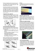
Particle size is dependent on pitch; most common size is 3-10 µm. To prevent short-circuits in the XY direction, particle size must decrease if pitch is decreased. About 100 - 1000 particles per square mm are present. ACF Tape The picture shows ACF tape peeled from the carrier tape. The conductive particles can be seen as small dots. Tape width is ~2 mm in this picture. The thickness of the adhesive is also dependent on the pitch. Thickness varies from 35 to as low as 18 µm for fine pitches. The reason for this is that fine pitches normally have lower trace heights: a trace height of 10 to...
Open the catalog to page 2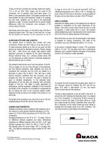
Tracks on the flex connector are normally made from copper, 12.5 or 25 µm thick. Plain copper can be used for the connection, but no oxidation must have taken place. It is better to use passivated copper. Gold plated contacts are the most reliable, but also more expensive. Solder or tin coatings are also seen; reliability can be good if the appropriate adhesive is used. Tin layers should be thin to prevent height differences within the connection area (because of the convex nature of the tin). Most flexes have three layers, on the bottom side of the flex a protective Kapton layer. This...
Open the catalog to page 3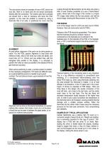
The next picture shows an example of how a HSC should not look like: there is no bevel and the foil bends downwards directly after the connection. The (matrix) glue that is pressed out should form a kind of meniscus and bend the HSC upwards. In this case the problem is caused by using a thermode that is too wide, or positioned too much near the edge. Looking through the flexconnector can be done only when a HSC is used. Another possibility is to use a “frame-freeze” option, where half of the image of the monitor is a frozen ITO image, taken before the flex was placed, and half the actual...
Open the catalog to page 4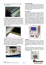
PROCESS EQUIPMENT Using the right equipment gives the highest possible yield and product quality. Equipment can vary from simple manual stations (suited for small series production and laboratory environments, see picture) to fully automated inline systems, for the highest production rates, up to one million products a year. The next picture shows a heatseal connector for a typical cellphone application. Laptop displays are a good example of ACF Bonding usage. A Chip On Foil technique is used here, one side of the foil is Hot Bar Reflow Soldered to a PCB and the other side is connected...
Open the catalog to page 5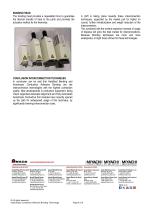
BONDING HEAD The bonding head provides a repeatable force to guarantee the thermal transfer of heat to the parts and provides the actuation method for the thermode. A shift is taking place towards these interconnection techniques, supported by the market pull for higher i/o counts, further miniaturization and weight reduction of the interconnection. This combined with the evident explosive increase of usage of displays will grow the total market for interconnections. Because Bonding techniques are more and more widespread, a bright future shines for these technologies. CONCLUSION...
Open the catalog to page 6All AMADA WELD TECH catalogs and technical brochures
-
Welding Applications
2 Pages

