- Catalogs
- AMADA WELD TECH Inc.
- resistance welding Fundamentals
- Products
- Catalogs
- News & Trends
- Exhibitions
resistance welding Fundamentals
1 /8Pages

resistance welding Fundamentals
1 /8Pages
Catalog excerpts
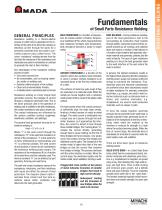
of Small Parts Resistance Welding GENERAL PRINCIPLES Resistance welding is a thermo-electric process in which heat is generated at the interface of the parts to be joined by passing an electrical current through the parts for a precisely controlled time and under a controlled pressure (also called force). The name “resistance” welding derives from the fact that the resistance of the workpieces and electrodes are used in combination or contrast to generate the heat at their interface. Key advantages of the resistance welding process include: • Very short process time • No consumables, such as brazing materials, solder, or welding rods • Operator safety because of low voltage • Clean and environmentally friendly • A reliable electro-mechanical joint is formed Resistance welding is a fairly simple heat generation process: the passage of current through a resistance generates heat. This is the same principle used in the operation of heating coils. In addition to the bulk resistances, the contact resistances also play a major role. The contact resistances are influenced by the surface condition (surface roughness, cleanliness, oxidation, and platings). The general heat generation formula for resistance welding is: Heat = I2 x R x t x K Where “I” is the weld current through the workpieces, “R” is the electrical resistance (in ohms) of the workpieces, “t” is the weld time (in hertz, milliseconds or microseconds), and “K” is a thermal constant. The weld current (I) and duration of current (t) are controlled by the resistance welding power supply. The resistance of the workpieces (R) is a function of the weld force and the materials used. The thermal constant “K” can be affected by part geometry, fixturing and weld force. The bulk and contact resistance values of the workpieces, electrodes, and their interfaces both cause and affect the amount of heat generated. The diagram (above right) illustrates three contact and four bulk resistance values, which, combined, help determine the heat generated. BULK RESISTANCE is a function of temperature. All metals exhibit a Positive Temperature Coefficient (PTC), which means that their bulk resistance increases with temperature. Bulk resistance becomes a factor in longer welds. HEAT BALANCE – During resistance welding, part of the heat generated is lost to the surroundings by conduction (heat transfer through solids), convection (heat lost from exposed surfaces by air-cooling), and radiation (does not require a medium). Heat balance is a function of part material and geometry, electrode material and geometry, polarity, and the weld schedule. The goal of good resistance welding is to focus the heat generated close to the weld interface at the spot where the weld is desired. CONTACT RESISTANCE is a function of the extent to which two surfaces mate intimately or come in contact. Contact resistance is an important factor in the first few milliseconds of a weld. In general, the highest resistance results in the highest heat assuming that the resistance welding power supply can produce sufficient energy to overcome the resistance. Thus, dissimilar parts and electrode combinations are preferred since their dissimilarity results in higher resistance. For example, conductive electrodes, e.g. copper, are used to weld resistive materials such as stainless steel or nickel, and resistive electrodes, e.g. molybdenum, are used to weld conductive materials, such as copper or gold. The surfaces of metal are quite rough if they are examined on a molecular scale. When the metals are forced together with a relatively small amount of force, some of the peaks make contact. On those peaks where the contact pressure is sufficiently high, the oxide layer breaks, forming a limited number of metal-to-metal bridges. The weld current is distributed over a large area as it passes through the bulk metal. However, as it approaches the interface, the current is forced to flow through these metallic bridges. This “necking down” increases the current density, generating enough heat to cause melting. As the first of these bridges melt and collapse, new peaks come into contact, forming new bridges and additional current paths. The resistance of the molten metal is higher than that of the new bridges so that the current flow transfers from bridge-to-bridge. This process continues until the entire interface is molten. When the current stops, the electrodes rapidly cool the molten metal, which solidifies, forming a weld. Exaggerated cross-section of two pieces of metal indicates formation of metallic bridges that result in high current density. Subsequent melting and the formation of new bridges allow the weld to be formed. To force the metals together, electrode pressure (force) provided by the weld head, is equally important. Heat, generated by the resistance of the workpieces to the flow of electricity, either melts the material at the interface or reduces its strength to a level where the surface becomes plastic. When the flow of current stops, the electrode force is maintained, for a fraction of a second, while the weld rapidly cools and solidifies. There are three basic types of resistance welding bonds: SOLID STATE BOND – In a Solid State Bond (also called thermo-compression Bond), dissimilar materials with dissimilar grain structure, e.g. molybdenum to tungsten, are joined using a very short heating time, high weld energy, and high force. There is little melting and minimum grain growth, but a definite bond and grain interface. Thus the materials actually bond while still in the “solid state.” The bonded materials typically exhibit excellent shear and tensile strength, but poor peel strength. RESISTANCE WELDING
Open the catalog to page 1
RESISTANCE WELDING FUSION BOND – In a Fusion Bond, either similar or dissimilar materials with similar grain structures are heated to the melting point (liquid state) of both. The subsequent cooling and combination of the materials forms a “nugget” alloy of the two materials with larger grain growth. Typically, high weld energies at either short or long weld times, depending on physical characteristics, are used to produce fusion bonds. The bonded materials usually exhibit excellent tensile, peel and shear strengths. REFLOW BRAZE BOND – In a Reflow Braze Bond, a resistance heating of a low temperature...
Open the catalog to page 2All AMADA WELD TECH Inc. catalogs and technical brochures
 TC-W100A
2 Pages
 MEA-100B
2 Pages
 MIB-300A/600A
2 Pages
 CD-A125A CD-A300A CD-A1000A
2 Pages
 Rotary Dial Index Systems
2 Pages
 AMADA WELD TECH
24 Pages
 HF-2700A / HF-2500A
4 Pages
 CD-V Series
2 Pages
 MD-A10000A/ MD-B5000A
2 Pages
 ISQ Series
3 Pages
 IPB-5000A-MU
2 Pages
 MFP60 for aws3
2 Pages
 MFP25 FRO AWS3
2 Pages
 Series 320
2 Pages
 newhorizon
3 Pages
 F120, F160, FD120
4 Pages
 KN-II Series
2 Pages
 MH Weld Head Range
4 Pages
 Accessries
9 Pages
 Laser Microfabrication
2 Pages
 ML-5120A
2 Pages
 Systems
16 Pages
 ML-5120
2 Pages
 DC29-UB29-UB29A
4 Pages
 LF Series Lasers
2 Pages
 SA2200 Dual Oven
2 Pages
 Laser Tube Cutting Systems
2 Pages
 Heat Staking
2 Pages
 Seam Laser Welder - 150W
2 Pages
 Systems Datasheet
16 Pages
 AX5000 Glovebox
2 Pages
 MX2000 Glovebox
2 Pages
 Benchmark AF8500 / AF 1250
2 Pages
 Pulsed-Heat Hot-Bar
10 Pages
 Benchmark SM8500
2 Pages
 vacuum bakeout oven
2 Pages
 Interposer Module
2 Pages
 UV Laser Marking Systems
2 Pages
 CO2 Laser Marking Systems
2 Pages
 Fiber Laser Micro Welders
2 Pages
 Sigma Laser Tube Cutter
2 Pages
 Laser Marker Motion
2 Pages
 Laser Welding Gloveboxes
2 Pages
 Thermocouple Welder - TCW
2 Pages
 Laser Accessories
7 Pages
 Alpha Series
2 Pages
 MX-2000 Glovebox Technical
2 Pages
 AX-5000 Glovebox
2 Pages
 Benchmark Accessories
9 Pages
 Thin Line Weld Heads
8 Pages
 Uniflow 4
2 Pages
 Pulsar
2 Pages
 LMC1 Laser Marker Motion
2 Pages
 LW300-600A
2 Pages
 LW50A-70-150A
2 Pages
 LW5-15-25A
2 Pages
 LF Series
2 Pages
 50 Series Weld Heads
4 Pages
 MH Series Weld Heads
4 Pages
 MG3
MG312 Pages
 MG3 Hot Bar Monitoring
3 Pages
 Sarcon and Kapton Modules
2 Pages
 Thin-line
8 Pages
 IS series
2 Pages
 ISB-300 A
2 Pages
 Accessoires
9 Pages
 DC25, UB25
4 Pages
 Fine Laser Cutting Datasheet
4 Pages
 laser markers and marker systems
16 Pages
 Bonding Heads
2 Pages


Archived catalogs
 MG3 UNIQUE PROCESS MONITORING
12 Pages
 Process Calibration Tools
2 Pages
 LaserCuttingSystems_Cut
4 Pages
 Pincer Weld Head - MFP-Z
3 Pages


- DC power supply
- Kiln
- AC/DC power supply
- Welding system
- Chamber kiln
- Electric furnace
- Automatic welding machine
- Marking machine
- Welder
- Laser marking machine
- Arc welder
- Tabletop power supply
- Metal welding machine
- Arc welding machine
- Stainless steel kiln
- Manual welding machine
- Precision welding machine
- Laser welding machine
- Benchtop marking machine