
Catalog excerpts
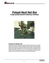
Pulsed-Heat Hot-Bar A high-quality Selective Soldering Technique PROCESS INTRODUCTION Pulsed-heated hot-bar reflow soldering is a selective soldering process where two pre-fluxed, solder coated parts are heated to a temperature sufficient to cause the solder to melt, flow, and solidify, forming a permanent electro-mechanical bond between the parts and solder. Pulse heated soldering differs from the traditional soldering process in that the reflow of solder is accomplished using a heating element called a “thermode” or “hot bar” which is heated and cooled down for each connection. Pressure is applied during the entire cycle including heating, reflow, and cooling. This technique is most commonly used to connect flex circuits to printed circuit boards.
Open the catalog to page 1
APPLICATION RANGE HBR soldering reflows solder by using a thermode that is heated and cooled for each connection. This 'selective' heating makes the process suitable for heat sensitive parts like CCD camera chips, connectors, etc. Furthermore, since pressure is applied during the entire cycle, the process is suitable for parts that might otherwise 'jump' loose during cooling using other soldering techniques. With HBR Soldering, all connections can be made simultaneously. Up to 200 leads or wires can be connected in one process cycle (typically around 15 seconds)! Making the connections...
Open the catalog to page 2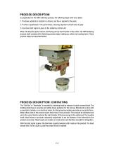
PROCESS DESCRIPTION In preparation for the HBR soldering process, the following steps need to be taken: 1.The base substrate is located in a fixture, and flux is applied to the pads. 2.The flex is positioned in the parts fixture, ensuring alignment of both sets of pads. 3.A process start signal is given to the soldering control unit. More info about the parts, fixtures and fluxing can be found further in this article. The HBR Soldering process itself consists of the following process steps: heating up, reflow and cooling down. These process steps are described below. PROCESS DESCRIPTION:...
Open the catalog to page 3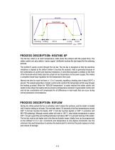
PROCESS DESCRIPTION: HEATING UP The hot-bar, which is at room temperature, holds down the product with the preset force. The solder control unit, also called a “power supply” (Uniflow4) receives the start signal for the soldering process. The Uniflow®4 sends current through the hot-bar. The hot-bar is designed so that the electrical resistance is highest at the bottom (where it touches the product). Heat is generated because of the combination of current and electrical resistance. A small thermocouple is welded on the front of the thermode which feeds back the actual hot-bar temperature to...
Open the catalog to page 4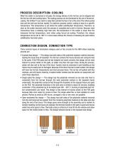
PROCESS DESCRIPTION: COOLING When the solder is connected on all pads, the energy delivery to the hot-bar can be stopped and the hot-bar will start cooling down. The cooling process can be shortened by the use of forced aircooling. The Uniflow®4 can switch a relay that controls the flow of air at the end of the reflow period and cool the joint and hot-bar rapidly. For optimum process control, cooling is done to a specific temperature. This temperature is set below the solder solidification temperature. Therefore, as soon as the solder becomes solid, the process is complete and a joint is...
Open the catalog to page 5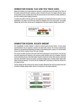
CONNECTION DESIGN: FLEX AND PCB TRACE SIZES Ideally, the flexible circuit pads should be narrower in width than that of the pads on the PCB. As the solder melts and the parts compress, solder is forced to the side. This design will allow space for the solder to flow on either side of the flex pad and will be more tolerant of solder quantity on the PCB, avoiding solder bridging problems. A smaller pad width on the flex will help with registration and alignment of the two parts. For most applications, the width of the PCB trace should be designed to be 55% of the pitch. This design reduces...
Open the catalog to page 6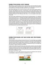
CONNECTION DESIGN: HEAT SINKING HBR soldering is a selective soldering process, meaning that only a part of the PCB will be heated, not the complete PCB (as would be the case in a reflow oven). This means that heat conduction from the connection area to the large and relative cold PCB is very, very important! Heat sinking differentials from one lead to the other are the most common design problem to overcome. Small differences will have a minimal effect, but any large thermal mass or heat conduction change along the joint area will cause inconsistency of lead (solder) temperature and solder...
Open the catalog to page 7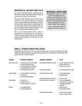
MATERIALS: SOLDER AND FLUX Flux has two important features: conducting heat to the solder and promoting wetting of the surfaces by cleaning and removal of surface oxides. The pulse-heated soldering process requires only a minimum of flux. No-clean fluxes are commonly used, sometimes RMA (Rosin Mild Activated). The use of a flux with low solids content is recommended. The lower the solids content, the less pollution of the hotbar. Any solvents present should be allowed to dry prior to commencing the soldering process. MATERIAL SUPPLIERS Amada Miyachi America is a system builder that supplies...
Open the catalog to page 8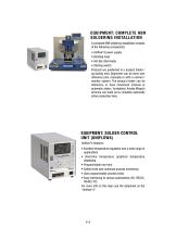
EQUIPMENT: COMPLETE HBR SOLDERING INSTALLATION A complete HBR soldering installation consists of the following components: • Uniflow®4 power supply • Bonding head • Hot-Bar (thermode) • Starting switch Products are positioned in a product holder / jig tooling nest. Alignment can be done over reference pins, manually or with a camera / monitor system. The product holder can be stationary, or have movement (manual or automatic slides / turntables). Amada Miyachi America can build up to complete automatic inline production lines. EQUIPMENT: SOLDER CONTROL UNIT (UNIFLOW4) Uniflow®4 features: •...
Open the catalog to page 9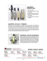
EQUIPMENT: BONDING HEAD • Force firing switch • Head-is-up limit switch for safety in automation • Adjustable force generation module • Accurate bearings for perfect hotbar guidance • Fine-adjustment for hot-bar plan parallelism EQUIPMENT: HOT-BAR / THERMODE Modern wire erosion techniques such as EDM and advanced materials have allowed the manufacture of precisely designed thermodes to suit most applications. Three-dimensional thermodes pass the current around the face and thus have zero voltage potential across the traces. These technological advances in machining processes produce designs...
Open the catalog to page 10All AMADA WELD TECH Inc. catalogs and technical brochures
-
TC-W100A
2 Pages
-
MEA-100B
2 Pages
-
MIB-300A/600A
2 Pages
-
CD-A125A CD-A300A CD-A1000A
2 Pages
-
Rotary Dial Index Systems
2 Pages
-
AMADA WELD TECH
24 Pages
-
HF-2700A / HF-2500A
4 Pages
-
CD-V Series
2 Pages
-
MD-A10000A/ MD-B5000A
2 Pages
-
ISQ Series
3 Pages
-
IPB-5000A-MU
2 Pages
-
MFP60 for aws3
2 Pages
-
MFP25 FRO AWS3
2 Pages
-
Series 320
2 Pages
-
newhorizon
3 Pages
-
F120, F160, FD120
4 Pages
-
KN-II Series
2 Pages
-
MH Weld Head Range
4 Pages
-
Accessries
9 Pages
-
Laser Microfabrication
2 Pages
-
ML-5120A
2 Pages
-
Systems
16 Pages
-
ML-5120
2 Pages
-
DC29-UB29-UB29A
4 Pages
-
LF Series Lasers
2 Pages
-
SA2200 Dual Oven
2 Pages
-
Laser Tube Cutting Systems
2 Pages
-
Heat Staking
2 Pages
-
Seam Laser Welder - 150W
2 Pages
-
Systems Datasheet
16 Pages
-
AX5000 Glovebox
2 Pages
-
MX2000 Glovebox
2 Pages
-
Benchmark AF8500 / AF 1250
2 Pages
-
Benchmark SM8500
2 Pages
-
vacuum bakeout oven
2 Pages
-
Interposer Module
2 Pages
-
UV Laser Marking Systems
2 Pages
-
CO2 Laser Marking Systems
2 Pages
-
Fiber Laser Micro Welders
2 Pages
-
Sigma Laser Tube Cutter
2 Pages
-
Laser Marker Motion
2 Pages
-
Laser Welding Gloveboxes
2 Pages
-
Thermocouple Welder - TCW
2 Pages
-
Laser Accessories
7 Pages
-
Alpha Series
2 Pages
-
MX-2000 Glovebox Technical
2 Pages
-
AX-5000 Glovebox
2 Pages
-
Benchmark Accessories
9 Pages
-
Thin Line Weld Heads
8 Pages
-
Uniflow 4
2 Pages
-
Pulsar
2 Pages
-
LMC1 Laser Marker Motion
2 Pages
-
LW300-600A
2 Pages
-
LW50A-70-150A
2 Pages
-
LW5-15-25A
2 Pages
-
LF Series
2 Pages
-
50 Series Weld Heads
4 Pages
-
MH Series Weld Heads
4 Pages
-
MG3
12 Pages
-
MG3 Hot Bar Monitoring
3 Pages
-
Sarcon and Kapton Modules
2 Pages
-
Thin-line
8 Pages
-
IS series
2 Pages
-
ISB-300 A
2 Pages
-
Accessoires
9 Pages
-
DC25, UB25
4 Pages
-
Fine Laser Cutting Datasheet
4 Pages
-
laser markers and marker systems
16 Pages
-
Bonding Heads
2 Pages
-
MG3 UNIQUE PROCESS MONITORING
12 Pages
-
Process Calibration Tools
2 Pages
-
LaserCuttingSystems_Cut
4 Pages
-
Pincer Weld Head - MFP-Z
3 Pages


