GC-NIP
1 /65Pages
GC-NIP
1 /65Pages
Catalog excerpts

GC-NIP Datasheet Version: 1.3 Date: 04/04/2017 AMAC ASIC- und Mikrosensoranwendung Chemnitz GmbH Kopernikusstr. 16 D-09117 Chemnitz Germany
Open the catalog to page 1
Revision history Date Initial version Operating mode changes Characteristic values updated Updated schematics change to new AMAC document layout © Copyright 2017 AMAC ASIC- und Mikrosensoranwendung Chemnitz GmbH Subject to change without prior notice. Our policy is one of continuous improvement, and consequently the equipment may vary slightly from the description and specifications in this publication. The specifications, illustrations and descriptions provided in this documentation are not binding in detail. No part of this publication may be reproduced in any form, or by any means, without...
Open the catalog to page 2
GC-NIP Datasheet
Open the catalog to page 3
GC-NIP Datasheet
Open the catalog to page 4
GC-NIP Datasheet
Open the catalog to page 5
GC-NIP Datasheet 1 Overview The 2-channel interpolation circuit GC-NIP serves to increase the resolution of absolute position and angular measuring systems with 2 sinusoidal output signals (nonius signal). Aside from the calculation of the absolute position, the GC-NIP may also operate as one- or two-channel incremental measuring system. The input signals are subjected to an AMAC-specific internal gain and offset control. Additionally, the phase deviation of the input signals can be adjusted statically by a digital potentiometer. Dividing the signal period of the input signals up to 8,192 times,...
Open the catalog to page 6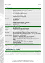
GC-NIP Datasheet 2 Features Interfaces Analog input Sinusoidal / cosinusoidal / reference (index) signals, differential or single-ended Adjustable amplification for 660 mVPP / 250 mVPP / 120 mVPP / 60 mVPP Input frequency max.130 kHz for nonius calculation; max. 90 kHz for interpolation 90° square-wave sequences (A/B/Z) Adjustable width of zero signal Z to ¼ or 1 period A/B Error signal; Interrupt signal for external processing Service signals for sensor adjustment 30-bit counter value for the interpolation channels Up to 22-bit resolution for the absolute position 9-bit sensor status information...
Open the catalog to page 7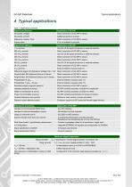
GC-NIP Datasheet Typical applications 4 Typical applications Table 1: Applications overview Signal form (Sensor) Sinusoidal, Voltage Direct connection of GC-NIP to sensor. Sinusoidal, Current Additional resistors required Reference- (Index-) Track Direct connection of GC-NIP to sensor. Square wave Signal Form (Sensor) Use GC-LS for signal conversion or external resistors. Direct connection of GC-NIP to sensor. Use GC-LS for signal conversion or external resistors. Direct connection of GC-NIP to sensor. Direct connection of GC-NIP to sensor. Use GC-LS for signal conversion or external resistors....
Open the catalog to page 8
GC-NIP Datasheet 5 Package Table 2: Pin list QFN64 Pin Name 1 2 3 Supply voltage analog +3.3V Output analog (Buffer) Monitor Output at instrumentation amplifier sine channel 2 Output analog (Buffer) Monitor Output at instrumentation amplifier cosine channel 2 Supply voltage digital +3.3V Input digital / Pull-Down Configuration analog filter / HWA<3> Input digital / Pull-Down Configuration analog filter / HWA<2> Input digital / Pull-Down SPI/BiSS/SSI: clock Input digital / Pull-Up Input digital / Pull-Down Supply voltage digital (IO) +3.3V Output Digital / Tristate Controller interface – clock...
Open the catalog to page 9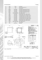
GC-NIP Datasheet Supply voltage analog +3.3V Input analog Input Reference Signal positive channel 2 Input analog Input Reference Signal negative channel 2 Input analog Input Reference Signal positive channel 1 Input analog Input Reference Signal negative channel 1 Output analog (Buffer) Input analog Sinusoidal signal at input, positive channel 1 Input analog Sinusoidal signal at input, negative channel 1 Input analog Cosinusoidal signal at input, negative channel 1 Input analog Cosinusoidal signal at input, positive channel 1 Input analog Cosinusoidal signal at input, positive channel 2 Input...
Open the catalog to page 10
GC-NIP Datasheet Start up Behaviour / Configuration Options 6 Start up Behaviour / Configuration Options 6.1 Reset During reset of the IC, the digital interface is selected (SPI or SSI/BiSS) and all registers are initialized with their default values. The initialization of the circuit is performed either from the internal EEPROM or from configuration pins. The internal EEPROM has to be programmed with a valid identifier at EEPROM address 0x00 to be used for configuration after reset. The configuration of the interpolation rate is either done from the EEPROM (if valid) or with a fixed interpolation...
Open the catalog to page 11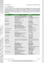
GC-NIP Datasheet Start up Behaviour / Configuration Options 6.2 Configuration The IC can be matched to most varied measuring systems and subsequent electronic systems by way of the configuration registers. If the IC is initialized using the integrated EEPROM or a serial interface (SPI/BiSS), full configuration possibilities are available. If the initialization is performed via the configuration pins, selected parameters can be set externally. Table 7 below provides an overview of the configuration possibilities of the GC-NIP. Detailed description of the configuration register set can be found...
Open the catalog to page 12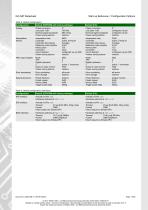
GC-NIP Datasheet Start up Behaviour / Configuration Options Table 8: Default configuration Configuration Default (EEPROM with factory settings) Phase correction Low pass -1dB Nominal signal amplitude Power saving options Phase correction Low pass -1dB Nominal signal amplitude Power saving options 0° configured via pin configured via pin inactive Interpolation Nonius Interpolation rate Controller Controller start values Reference mark position Nonius pitch Correction Count direction Power saving options 8000 active, timing 01 Average at 45° 125 none configured via pin DIR inactive Interpolation...
Open the catalog to page 13
GC-NIP Datasheet Functional description 7 Functional description 7.1 Input amplifier / Low pass filter The GC-NIP incorporates six instrumentation amplifiers with adjustable gain factors. Incremental encoders with voltage interface and measuring bridges can be connected directly. Sensors with current-interface are adapted by way of a simple external circuit (see 11.1). The IC operates with both, single-ended and differential input signals. The amplification is identical for all signals of the sensor (sinusoidal, cosinusoidal, index/reference). To adapt the GC-NIP to customized sensors, the mean...
Open the catalog to page 14All AMAC ASIC - und Mikrosensoranwendung Chemnitz GmbH catalogs and technical brochures
 AIP40
AIP4019 Pages
 GC-IP200
31 Pages
 GC-IP201 / GC-IP201(B)
59 Pages
 GC-IP1000B
33 Pages
 AM-IP4k
54 Pages
 AM-CVC2D
36 Pages
 Level shifter GC-LS
13 Pages
 GC-IP2000
51 Pages
- Acceleration sensor
- Single-axis accelerometer
- Programmable amplifier
- Photodiode microchip
- 2-channel amplifier
- Vibrating accelerometer
- Digital output accelerometer
- Digital microchip
- Power integrated circuit
- Programmable integrated circuit
- Interpolator
- Measuring system interpolator
- Interpolator with ABZ interface
- Interpolator with BiSS interface