- Catalogs
- AMAC ASIC - und Mikrosensoranwendung Chemnitz GmbH
- GC-IP201 / GC-IP201(B)
GC-IP201 / GC-IP201(B)
1 /59Pages
GC-IP201 / GC-IP201(B)
1 /59Pages
Catalog excerpts

AMAC ASIC- und Mikrosensoranwendung Chemnitz GmbH Kopernikusstr. 16 D-09117 Chemnitz Germany
Open the catalog to page 1
Revision History Date First Version / preliminary version Update for Engineering Samples Pin list and Block diagram new Updated chapter EEPROM Update of the input signal parameters and maximum input signal frequency Update of the electrical specification parameters change document layout according to AMAC CI © Copyright 2017 AMAC ASIC- und Mikrosensoranwendung Chemnitz GmbH Subject to change without prior notice. Our policy is one of continuous improvement, and consequently the equipment may vary slightly from the description and specifications in this publication. The specifications, illustrations...
Open the catalog to page 2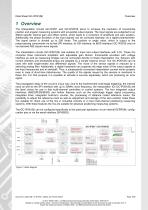
1 Overview The interpolation circuits GC-IP201 and GC-IP201B serve to increase the resolution of incremental position and angular measuring systems with sinusoidal output signals. The input signals are subjected to an AMAC-specific internal gain and offset control, which leads to a correction of amplitude and zero position. Additionally, the phase deviation of the input signals can be corrected statically via a digital potentiometer. The signal period is divided up to 256 times. The position or angle value, which is output to the preprocessing components via its fast SPI interface, its SSI interface,...
Open the catalog to page 6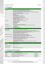
2 Features Interfaces Analog input - Sine- / Cosine- / Reference signal; differential or single-ended - Nominal amplitude configurable to 660mVpp / 330mVpp / 160 mVpp / 50mVpp (corresponds 1Vpp / 500mVpp / 240mVpp / 80mVpp at 5V systems) - Maximum input frequency 440kHz for all resolutions (410 kHz with internal controller enabled) - 90°-square wave sequences (A/B/Z) - Adjustable width of the index signal Z of ¼ or 1 period A/B - Error signal - Interrupt signal for µC - Additional signals for sensor adjustment - 30 Bit counting value / 16 Bit multi-turn value - Data rate up to 500 000 measuring...
Open the catalog to page 7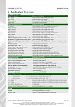
Application Overview 4 Application Overview Table 1: Application overview Signal Form (Sensor) Sine, voltage Direct connection of GC-IP201(B) to the sensor Sine, current Additional resistor circuit required Reference signal Direct connection of GC-IP201(B) to the sensor Square wave Signal Specification (Sensor) Direct connection via GC-LS or via special resistor circuit Direct connection of GC-IP201(B) to the sensor Direct connection of GC-IP201(B) to the sensor Direct connection of GC-IP201(B) to the sensor Direct connection via GC-LS or via special resistor circuit Direct connection of GC-IP201(B)...
Open the catalog to page 8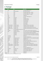
5 Package Table 2: Pin list QFN40 Pin Name Power supply voltage analog +3.3V Output analog (Buffer) Mean voltage for sensor use ADC reference voltage 0.625V – C external ADC reference voltage 1.575V – C external ADC reference voltage 1.1V – C external Analog ground Power supply voltage analog +3.3V Output analog Test output Input analog Input reference positive Input analog Input reference negative Input analog Input cosine positive Input analog Input cosine negative Input analog Input sine positive Input analog Input sine negative Input digital / Pull down Configuration interval time / hardware...
Open the catalog to page 9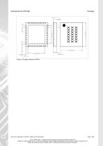
Figure 2: Package dimension QFN40 Document: 4420x-DB-1-2-E-IP201_AMAC_20170125_Patent © 2017 AMAC ASIC- und Mikrosensoranwendung Chemnitz GmbH Date: 25/01/2017 Subject to change without notice · Any kind of duplication, reprocessing and translation of this document as well as excerpts from it require the written permission of AMAC ASIC- und Mikrosensoranwendung Chemnitz GmbH.
Open the catalog to page 10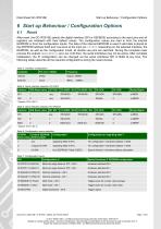
Start up Behaviour / Configuration Options 6 Start up Behaviour / Configuration Options 6.1 After reset, the GC-IP201(B) selects the digital interface (SPI or SSI/BiSS) according to the input pins and all registers are initialised with their default values. The configuration values are read in from the internal EEPROM or from the configuration inputs. The data of the internal EEPROM is used if valid data is stored at the EEPROM address 0x00 and Low-level at the input pin CFGPIN. Depending on the selected interface, the EEPROM, as well as the configuration mode, all double use pins are switched....
Open the catalog to page 11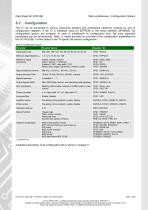
Start up Behaviour / Configuration Options The IC can be connected to various measuring systems and subsequent electronic systems by way of configuration registers. If the IC is initialised using an EEPROM or the serial interface (SPI/BiSS), full configuration options are available. In case of initialisation by configuration pins, the most important parameters can be set externally. Table 8 below provides an overview of the configuration possibilities for the GC-IP201(B). Further tables 9 and 10 specify the factory configuration. Table 8: Configuration options Parameter Possible Values Interpolation...
Open the catalog to page 12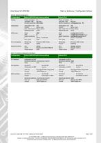
Start up Behaviour / Configuration Options Table 9: Default configuration Configuration Default (EEPROM with factory setting) Phase correction 0° Low pass -1dB 450 kHz Nominal amplitude 660 mVpp Phase correction 0° Low pass -1dB 450 kHz Nominal amplitude configurable via Pin Interpolation rate Control Start value Control Reference point 256 active, slow Mean values at 45° Interpolation rate Control Start value Control Reference point 256 active, slow Mean values at 45° Mode TPP Digital hysteresis Z Error case ABZ 0 1 active, 1 increment Hold Mode TPP Digital hysteresis Z Error case configurable...
Open the catalog to page 13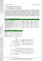
Input amplifier / Low pass filter The GC-IP201 / GC-IP201(B) incorporates three instrument amplifiers with adjustable gain factors. Incremental encoders with a voltage interface and measuring bridges can be connected directly. Sensors with current interface are adapted by way of a simple external circuit (see also 11.1) The IC operates with both single-ended and differential input signals. The amplification is identical for all signals of the sensor (sinusoidal, cosinusoidal, index/reference). To adapt the GC-IP201 / GC-IP201(B) to customised sensors, the mean voltage of the instrument amplifier...
Open the catalog to page 14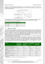
The inputs of the instrumentation amplifiers have an input level limitation of Vin=0.35 V…VDDA-1.00 V. Therefore, the operation area for the gain setting “00” (V NOM = 660 mVpp) is limited by the common mode voltage at the analog inputs. Figure 5: CMIR (input signals) The following table shows some possible combinations of common-mode voltage and VDDA in case of maximum amplitude for single-ended signals (800 mVpp) and maximum offset (±70 mV) exemplary: Table 13: Example Common mode input voltage (CMIR) VDDA Common mode voltage (Min) Common mode voltage (Max) Signal correction The input signals...
Open the catalog to page 15All AMAC ASIC - und Mikrosensoranwendung Chemnitz GmbH catalogs and technical brochures
 AIP40
AIP4019 Pages
 GC-IP200
31 Pages
 GC-IP1000B
33 Pages
 GC-NIP
65 Pages
 AM-IP4k
54 Pages
 AM-CVC2D
36 Pages
 Level shifter GC-LS
13 Pages
 GC-IP2000
51 Pages
- Acceleration sensor
- Single-axis accelerometer
- Programmable amplifier
- Photodiode microchip
- 2-channel amplifier
- Vibrating accelerometer
- Digital output accelerometer
- Digital microchip
- Power integrated circuit
- Programmable integrated circuit
- Interpolator
- Measuring system interpolator
- Interpolator with ABZ interface
- Interpolator with BiSS interface