GC-IP2000
1 /51Pages

GC-IP2000
1 /51Pages
Catalog excerpts

GC-IP2000 Datasheet Version: 1.4 Date: 05/01/2017 AMAC ASIC- und Mikrosensoranwendung Chemnitz GmbH Kopernikusstr. 16 D-09117 Chemnitz Germany
Open the catalog to page 1
Revision Overview Date First version (preliminary), provisional pin assignment Package fixed Some Parameter fixed Figures added Application notes added Temperature range Parameters Pin XA added Parameters reference comparator added Package drawings added Nominal amplitude 80mVpp changed to 75 mVpp Further product links added change to new AMAC document layout © Copyright 2017 AMAC ASIC- und Mikrosensoranwendung Chemnitz GmbH Subject to change without prior notice. Our policy is one of continuous improvement, and consequently the equipment may vary slightly from the description and specifications...
Open the catalog to page 2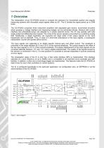
1 Overview The interpolation circuit GC-IP2000 serves to increase the resolution for incremental position and angular measuring systems with sinusoidal output signals offset by 90°. The IC divides the signal period up to 2048 times. The GC-IP2000 comprises three instrument amplifiers with adjustable gain factors. Incremental encoders which possess a voltage interface and measuring bridges can be connected directly. Sensors with current interface and photodiode-arrays are adapted by a simple external circuit. The IC may operate with both single-ended and differential input signals. The noise of...
Open the catalog to page 6
2 Features Table 1 Overview Analog Part Analog input - Sinusoidal / cosinusoidal / reference (index) signals; differential or single ended - Adjustable amplification for 1 Vpp / 500 mVpp / 250 mVpp / 75 mVpp - Input frequency max. 260 kHz for all resolutions Digital Part Interpolation rate Output signals - 30-bit counter value via serial interface (SPI) - Up to 500000 measurement values per second - 90° square-wave sequences (A/B/Z) - Error signal - Interrupt signal to the µC - Auxiliary signals for sensor adjustment Signal correction - AMAC-specific digital controller for the offset, control...
Open the catalog to page 7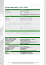
3 Typical applications of GC-IP2000 Signal Form (Sensor) Sinusoidal, Voltage Direct connection of GC-IP2000 to sensor Sinusoidal, Current Additional resistors required Reference (Index)-Track Direct connection of GC-IP2000 to sensor Square wave ICs are not suitable in principle; However, special resistor network and configuration allow using of the internal interpolation counter Signal Form (Sensor) Direct connection of GC-IP2000 to sensor Direct connection of GC-IP2000 to sensor Direct connection of GC-IP2000 to sensor Direct connection of GC-IP2000 to sensor Additional resistors required Differential...
Open the catalog to page 8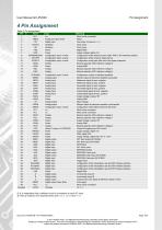
Name N.C. NRES TM XA/CLK XB VSS VDD Z4/IRBIN/HWA3 CFGTPP CFGFILT RS25 VSSA RSL RSH CFGGAIN SMON REFN REFP SINN SINP COSN COSP VDDA VSSA V0 CMON MODE N.C. N.C. RC25 RCL VDDA VSSA RCH LED VPROG VSSIO VDDIO MISO MOSI SEN SCK ECS ECK EDI EDO TRG IR2/HWA2 IR1/HWA1 IR0/HWA0 VSS A B Z NERR N.C. DVSS Type n.c. Analog I/O; Open Drain Digital input Oscillator Oscillator Power Power Configuration input, 4-value Configuration input, 4-value Configuration input, 4-value Analog Power Analog Analog Meaning Must not be connected Reset Test mode; Connect to VSS! Clock cycle Clock cycle Digital GND Supply voltage,...
Open the catalog to page 9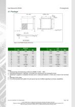
Figure 2: GC-IP2000 Package Dimensions Notes 1 Dimensioning and tolerancing conform to ASME Y14.5M – 1994. 2 Controlling dimensions: millimeter. Converted inch dimensions not necessarily exact. 3 Dimension b applies to metallized terminal and is measured between 0.15mm and 0.30mm from terminal tip. 4 Drawings not to scale. 5 The recommended land pattern for pcb layout may be modified regarding to process capabilities. Document: 44000-DB-1-4-E-IP2000-AMAC © 2017 AMAC ASIC- und Mikrosensoranwendung Chemnitz GmbH Date: 05/01/2017 Subject to change without notice · Any kind of duplication, reprocessing...
Open the catalog to page 10
Figure 3: GC-IP2000 Foot print Figure 4: GC-IP2000 Carrier tape Document: 44000-DB-1-4-E-IP2000-AMAC © 2017 AMAC ASIC- und Mikrosensoranwendung Chemnitz GmbH Date: 05/01/2017 Subject to change without notice · Any kind of duplication, reprocessing and translation of this document as well as excerpts from it require the written permission of AMAC ASIC- und Mikrosensoranwendung Chemnitz GmbH.
Open the catalog to page 11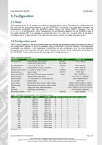
5 Configuration 5.1 Reset After resetting of the IC, all registers are initialised with their default values. Thereafter, the configuration pins are read into the appropriate registers. If a valid EEPROM is connected, the configuration registers are subsequently overwritten with the EEPROM values. During the whole RESET sequence, the pin MISO/nWAIT is maintained at L level. Subsequently, the configuration registers can be modified by way of the serial interface SPI. It is possible to connect the pins NERR and NRES to each other to be able to reconfigure the IC in case of error. In this case,...
Open the catalog to page 12
Table 5 Configuration of the reference point Reference-point width CFG1 - Z4 Pin Z4 Reference-point processing 4 increments = 1 period See Section 6.2.2 Table 6 Pin Z4/IRBIN/HWA3 Pin Z4/IRBIN/HWA3 Interpolation rate VSS Reference-point width Table 7 Configuration of the output signals ABZ output signals CFG1 - MODE (1:0) Sensor adjustment 2 See Section 6.7 Table 8 Configuration of the signal amplitude (nominal value) Input signals CFG1- GAIN(1:0) Table 9 Configuration of the minimum edge interval Min. edge interval tpp CFG1 – TPP(2:0) Table 10 Configuration of the hysteresis Pin CFGFILT CFG1-...
Open the catalog to page 13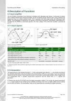
6 Description of Functions 6.1 Input amplifier The GC-IP2000 incorporates three instrument amplifiers with adjustable gain factors. Incremental encoders with a voltage interface and measuring bridges can be connected directly. Sensors with current interface are adapted by way of a simple external circuit. The IC operates with both single-ended and differential input signals. The amplification is identical for all signals of the sensor (sinusoidal, cosinusoidal, index/reference). To adapt the GC-IP2000 to customised sensors, the mean voltage of the instrument amplifier is provided at pin V0. Figure...
Open the catalog to page 14All AMAC ASIC - und Mikrosensoranwendung Chemnitz GmbH catalogs and technical brochures
 AIP40
AIP4019 Pages
 GC-IP200
31 Pages
 GC-IP201 / GC-IP201(B)
59 Pages
 GC-IP1000B
33 Pages
 GC-NIP
65 Pages
 AM-IP4k
54 Pages
 AM-CVC2D
36 Pages
 Level shifter GC-LS
13 Pages
- Acceleration sensor
- Single-axis accelerometer
- Programmable amplifier
- Photodiode microchip
- 2-channel amplifier
- Vibrating accelerometer
- Digital output accelerometer
- Digital microchip
- Power integrated circuit
- Programmable integrated circuit
- Interpolator
- Measuring system interpolator
- Interpolator with ABZ interface
- Interpolator with BiSS interface