GC-IP1000B
1 /33Pages
GC-IP1000B
1 /33Pages
Catalog excerpts
GC-IP1000B Datasheet Version: 2.3 Date: 18/01/2017 AMAC ASIC- und Mikrosensoranwendung Chemnitz GmbH Kopernikusstr. 16 D-09117 Chemnitz Germany
Open the catalog to page 1
Revision History Date change to new AMAC document layout © Copyright 2017 AMAC ASIC- und Mikrosensoranwendung Chemnitz GmbH Subject to change without prior notice. Our policy is one of continuous improvement, and consequently the equipment may vary slightly from the description and specifications in this publication. The specifications, illustrations and descriptions provided in this documentation are not binding in detail. No part of this publication may be reproduced in any form, or by any means, without the prior written permission of AMAC ASIC- und Mikrosensoranwendung Chemnitz GmbH. All...
Open the catalog to page 2
1 Overview The interpolation circuit GC-IP1000B serves to increase the resolution for incremental position and angular measuring systems with sinusoidal output signals offset by 90°. The IC divides the signal period up to 1000 times. The GC-IP1000B comprises three instrument amplifiers with adjustable gain factors. Incremental encoders which possess a voltage interface, and measuring bridges can be connected directly. The IC may operate with both single-ended and differential input signals. The input signals are subjected to an AMAC-specific internal gain and offset control. The amplitude is...
Open the catalog to page 6
2 Features Table 1: Features Features Analog input 3 channels differential: sine/cosine/reference signal Standard connection 1Vpp (differential) Input ranges: 100mVpp, 120mVpp, 145mVpp (differential) Single-ended input 2.0Vpp Input frequency of up to 110kHz Signal correction Automatic offset and amplitude controller Digital potentiometer for phase Interpolation rate Output for measuring values 28-bit counting value 90° square-wave sequences or up/down counting pulses resp. Error signal Configuration options Via configuration pins Via serial interface (SPI) Via EEPROM For configuration and measuring-value...
Open the catalog to page 7
3 Pin Assignment Table 2: Pin Assignment Pin Digital output / COUT EEPROM: data output Digital output / COUT EEPROM: clock Digital output / CODO Digital input / TTLIN Digital input / TTLIN Digital input / TTLIN Digital input / TTLIN Digital input / TTLIN Digital input / TTLIN Digital input / TTLIN Digital input / TTLIN Digital input / TTLIN Configuration interval time 5) Digital input / TTLIN Configuration interval time 5) Digital input / TTLIN Configuration interval time5) DProg 3 *) Digital input / TTLIN Configuration interpolation rate 5) DProg 2 *) Digital input / TTLIN Configuration interpolation...
Open the catalog to page 8
Analog Output Analog Output Analog Output Analog Output Analog power supply voltage +5V Analog input Analog input Input cosine negative Analog input Input cosine positive Analog Output Analog output cosine Backup capacitor, ADC reference voltage Backup capacitor, ADC reference voltage Digital input / CINPU Configuration gain Digital input / CINPD Configuration gain Programming voltage Programming ground Digital ground Digital power supply voltage +5V Digital input / TTLIN Digital input / TTLIN Digital output / COUT Digital output / COUT Digital output / COUT EEPROM: enable Digital input / TTLIN...
Open the catalog to page 9
4 Configuration 4.1 Reset After a reset of the IC all registers will be initialised with default values. After that the configuration pins will be read in. Those values overwrite the default values. If a valid EEPROM is connected to the IC the EEPROMvalues will overwrite pin values. During the whole reset process the pin SDO/RDY will be held low. After that the configuration register can be changed via the serial interface SPI. For starting a new configuration in case of an error it is possible to connect the pins NRES and NERR. If they are connected, the reset signal will be held by the „NERR-chain“...
Open the catalog to page 10
4.3 Configuration Pins The IC can be adapted to various measurement systems and further processing electronics by using the configuration registers. All configuration possibilities can be used if the IC will be initialised via EEPROM respectively SPI interface. The most important parameters can also be adjusted via external pin configuration. The following tables show these possibilities for configuration of GC-IP1000B. Table 4: Configuration Possibilities Parameter Interpolation rate Min. edge distance tpp Reference point processing Enable, Disable Nominal signal amplitude Glitch filter Enable,...
Open the catalog to page 11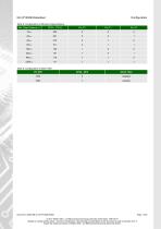
Table 8: Configuration of Minimum Edge Distance Min. Edge Distance tpp Table 9: Configuration of Glitch Filter Pin GFE Glitch Filter Document: 43000-DB-2-3-E-IP1000B-AMAC © 2017 AMAC ASIC- und Mikrosensoranwendung Chemnitz GmbH Date: 18/01/2017 Subject to change without notice · Any kind of duplication, reprocessing and translation of this document as well as excerpts from it require the written permission of AMAC ASIC- und Mikrosensoranwendung Chemnitz GmbH.
Open the catalog to page 12
5 Function 5.1 Input Amplifier The GC-IP1000B incorporates three instrument amplifiers with adjustable gain factors. Incremental encoders with a voltage interface and measuring bridges can be connected directly. The IC operates with both singleended and differential input signals. The amplification is identical for all signals of the sensor (sine, cosine, index/reference). To adapt the GC-IP1000B to customised sensors, the common reference voltage of the instrument amplifier is provided at pin V0. Figure 2: Input signals Figure 3: Input signals Table 10: Gain Configuration G1 Gain (nominal) Input...
Open the catalog to page 13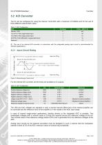
5.2 A/D Converter The IC can be configured for using the internal 12-bit ADC with a maximum of 343kS/s and for the use of three different external ADC types. Table 11: ADC Configuration ADC AD7475 (12 Bit, differential / single-ended input) The use of an internal A/D converter in conjunction with the integrated analog input circuit is recommended for standard applications. 5.2.1 Input Circuit Rating Figure 4: Dimensioning of input circuit For the internal A/D converter, all the levels are available at IC outputs. Table 12: ADC Configuration Pin Nominal Value Positive reference voltage sine...
Open the catalog to page 14All AMAC ASIC - und Mikrosensoranwendung Chemnitz GmbH catalogs and technical brochures
 AIP40
AIP4019 Pages
 GC-IP200
31 Pages
 GC-IP201 / GC-IP201(B)
59 Pages
 GC-NIP
65 Pages
 AM-IP4k
54 Pages
 AM-CVC2D
36 Pages
 Level shifter GC-LS
13 Pages
 GC-IP2000
51 Pages
- Acceleration sensor
- Single-axis accelerometer
- Programmable amplifier
- Photodiode microchip
- 2-channel amplifier
- Vibrating accelerometer
- Digital output accelerometer
- Digital microchip
- Power integrated circuit
- Programmable integrated circuit
- Interpolator
- Measuring system interpolator
- Interpolator with ABZ interface
- Interpolator with BiSS interface