AM-IP4k
1 /54Pages
AM-IP4k
1 /54Pages
Catalog excerpts

AM-IP4k Datasheet Version: Date: AMAC ASIC- Mikrosensoranwendung Chemnitz GmbH Kopernikusstr. 16 D-09117 Chemnitz Germany
Open the catalog to page 1
Revision History Date First Version At 2 Features Analogue input range 220 kHZ Figure 1 Block diagram ink word changed to inc. Figure 2 Functional block diagram ink word changed to inc. Overview. Switching analogue filter deleted and modified to low-pass. Figure 4 Input signals (single-ended) update. U to V. Figure 5 Input signals differential update. U to V. Figure 11 Reference signal MVAL(ZMODE) updated to CFG3/ZMODE 01 Figure 21 Mnimum circuit of the AM-IP4K added Table 1: Pin assignment AM-IP4k QFN56 Pin assignment, revised Instrument amplifier changed to instrumentation amplifiers 7.2.2...
Open the catalog to page 2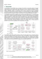
1 Overview The interpolation circuit AM-IP4k serves to increase the resolution of incremental position and angular measuring systems with sinusoidal output signals offset by 90°. The input signals are subjected to an AMACspecific internal gain and offset control, which automatically leads to a correction of amplitude and zero position. Additionally correction of concentricity errors as well as signal form errors are integrated. Furthermore the phase deviation of the input signals can be corrected statically via a digital potentiometer. By dividing the signal period up to 4096 times a position...
Open the catalog to page 6
2 Features Interfaces Analogue input - Sine- / Cosine- / Reference signal: differential or single-ended - Nominal amplitude configurable to 1 Vpp / 500 mVpp / 250 mVpp / 75 mVpp - Maximum input frequency up to 220 kHz - 90° square wave sequences (A/B/Z) - Adjustable width of the index signal Z of ¼ or 1 period A/B - Error signal - Interrupt signal for µC - Additional signals for sensor adjustment - 30 bit count value / 16 bit multi-turn value - Data rate up to 500,000 measured values/s - 9 bit signal monitoring - Compatible with standard SPI: 16 bit, MSB first, up to 25 MHz - Signal filter for...
Open the catalog to page 7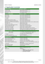
Application overview 4 Application overview Signal form (Sensor) Sinusoidal, voltage Direct connection of AM-IP4k to sensor Sinusoidal, current Additional resistors required Reference (index) track Direct connection of AM-IP4k to sensor Square wave Signal specification (sensor) Direct connection of AM-IP4k to sensor Direct connection of AM-IP4k to sensor Direct connection of AM-IP4k to sensor Direct connection of AM-IP4k to sensor Additional resistors required Differential signal, DC reference voltage Direct connection of AM-IP4k to sensor Single-ended, DC reference source inside sensor Direct...
Open the catalog to page 8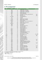
Name SINP SINN COSP COSN REFP REFN V5V VSS VDD CLK_CLKSEL TM2 TM TST_0B TST_0A MOSI_SLI SEN SCK_MA NSS MISO_SLO NERR VSSO VDDO A B Z HWA3 1) HWA2 1) HWA1 1) HWA0 1) TRG ZERO TEACH NRES VDD VSS LDP LDN OPO OPI VDDA VSSA SMON CMON V1P1 VRH ADIN ADIP VRM VRL VDDA VSSA TSTP TSTP2 TSTP1 EXPOSED Function Quadrature signal 1 – Sine positive Quadrature signal 1 – Sine negative Quadrature signal 2 – Cosine positive Quadrature signal 2 – Cosine negative Reference signal positive Reference signal negative Supply voltage analogue (Mean voltage single-ended) Digital GND Supply voltage digital Clock selection/Clock...
Open the catalog to page 9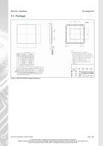
Figure 3: AM-IP4k QFN56 Package Dimensions © 2020 AMAC ASIC- und Mikrosensoranwendung Chemnitz GmbH Date: 05/02/2020 Subject to change without notice · Any kind of duplication, reprocessing and translation of this document as well as excerpts from it require the written permission of AMAC ASIC- und Mikrosensoranwendung Chemnitz GmbH.
Open the catalog to page 10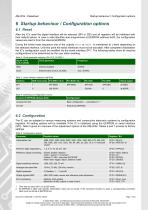
Startup behaviour / Configuration options 6 Startup behaviour / Configuration options 6.1 Reset After the IC’s reset the digital interface will be selected (SPI or SSI) and all registers will be initialised with their default values. In case a valid identifier was programmed at EEPROM address 0x00, the configuration values are read in from the internal EEPROM. During the whole reset sequence one of the outputs MISO or NERR is maintained at L-level depending on the selected interface. Until this point the serial interfaces must not be activated. After completed initialisation the IC’s configuration...
Open the catalog to page 11
Startup behaviour / Configuration options Possible values Phase correction ± 10° Step size 0.3125°, ±5° Step size 0.15625° Gain controller Default setting / time constant / enable, disable CNTRLG, CFG2 / GAINCTL, DISCTL Offset controller Default setting / time constant / enable, disable CNTRLO, CFG2 / OFFSCTL, DISCTL Hardware address Special functions Trigger edge Teach active / inactive Measuring timer Counter zero position (preset) CFG2 / TRGSLP CFG2 / TEAEN CFG3 / VT(1:0),T(7:0) PRE_ST, PRE_MT Interface configuration Data format of position values CFGSSI / SSI20, MTBIT (1:0), GRAY, STBIT (4:0)...
Open the catalog to page 12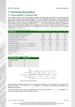
Functional description 7 Functional description 7.1 Input amplifier / Low-pass filter The AM-IP4k contains three instrumentation amplifiers with adjustable gain factors. Incremental encoders with a voltage interface and measuring bridges can be connected directly. Sensors with current interface are adapted by a simple external circuit (see chapter 11.1). The IC is able to operate with both single-ended and differential input signals. There is an identical amplification of all sensor signals (sine, cosine, reference). The mean voltage of the instrumentation amplifier at pin V1P1 can be used to...
Open the catalog to page 13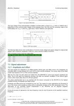
Functional description Vinput VDIFF= SINP-SINN Headroom to control amplitude+offset Headroom to control amplitude+offset Figure 5: Input signals (differential) The input voltage of the instrumentation amplifiers is limited within a range of Vinput= 0.65 V to VDDA-0.45 V. Depending on the common-mode voltage at the analogue input, this may limit the operating range of the GAIN setting “00” (VNOM = 1000 mVpp), gain factor. Fehler: Referenz nicht gefunden Figure 6: CMIR (Input signals) The following table shows some combinations of common-mode voltage and supply voltage for single-ended signals3...
Open the catalog to page 14All AMAC ASIC - und Mikrosensoranwendung Chemnitz GmbH catalogs and technical brochures
 AIP40
AIP4019 Pages
 GC-IP200
31 Pages
 GC-IP201 / GC-IP201(B)
59 Pages
 GC-IP1000B
33 Pages
 GC-NIP
65 Pages
 AM-CVC2D
36 Pages
 Level shifter GC-LS
13 Pages
 GC-IP2000
51 Pages
- Acceleration sensor
- Single-axis accelerometer
- Programmable amplifier
- Photodiode microchip
- 2-channel amplifier
- Vibrating accelerometer
- Digital output accelerometer
- Digital microchip
- Power integrated circuit
- Programmable integrated circuit
- Interpolator
- Measuring system interpolator
- Interpolator with ABZ interface
- Interpolator with BiSS interface