AIP40
1 /19Pages
AIP40
1 /19Pages
Catalog excerpts
AIP40 Datasheet Version: 1.5 Date: 26/01/17 AMAC ASIC- und Mikrosensoranwendung Chemnitz GmbH Kopernikusstr. 16 D-09117 Chemnitz Germany
Open the catalog to page 1
Revision History Date Data Sheet RoHS Version Update Application Notes change to new AMAC document layout © Copyright 2017 AMAC ASIC- und Mikrosensoranwendung Chemnitz GmbH Subject to change without prior notice. Our policy is one of continuous improvement, and consequently the equipment may vary slightly from the description and specifications in this publication. The specifications, illustrations and descriptions provided in this documentation are not binding in detail. No part of this publication may be reproduced in any form, or by any means, without the prior written permission of AMAC ASIC-...
Open the catalog to page 2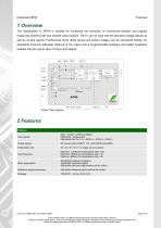
1 Overview The Interpolation IC AIP40 is suitable for increasing the resolution of incremental position and angular measuring systems with sine shaped output signals. The IC can be used with the standard voltage signals as well as current signals. Furthermore photo diode arrays and sensor bridges can be connected directly. An adjustable minimum A/B-edge distance at the output and a programmable analogue and digital hysteresis enables also the use in case of noisy input signals. Figure 1 Block diagram 2 Features Features Input signals Sine- / cosine- / reference Signal Differential / single-ended...
Open the catalog to page 5
Ordering Information 3 Ordering Information Product Type Article Number Interpolation circuit GC-AIP40, TSSOP20, RoHS conform Input analogue Input cosine positive Input analogue Input reference signal negative Input analogue Input reference signal positive Gain adjustment Supply voltage +5V analogue Ground analogue and digital Supply voltage +5V digital Output digital Output reference signal (index) Output digital Output digital Configuration analogue/digital Configuration of the minimum A/B-edge distance Configuration analogue/digital Configuration of analogue and digital hysteresis Output analogue...
Open the catalog to page 6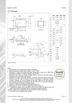
Notes: 1 All dimensions are in millimeters (angles in dedrees) 2 Dimensioning and tolerancing per asme Y14.5M – 1994 3 Dimension 'D' does not include mold flash, protrusions or gate burrs. Mold flash, protrusions or gate burrs shall not exceed 0.15 per side. 4 Dimension 'E1' does not include interlead flash or protrusion. Interlead flash or protrusion shall not exceed 0.25 per side. 5 Dimension 'b' does not include dambar protrusion. Allowable dambar protrusion shall be 0.08 mm total in excess of the 'b' dimension at maximum material condition. Dambar can not be located on the lower radius of...
Open the catalog to page 7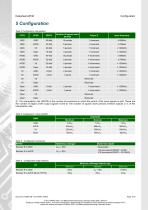
5 Configuration Table 2 Configuration interpolation CFG1 Number of square wave periods Input frequency i The interpolation rate (IRATE) is the number of increments in which the period of the input signals is split. These are the number of edges at the output signals A and B. The number of square wave periods at these outputs is ¼ of the interpolation rate. Table 3 Configuration input amplifier Amplitude Table 4 Configuration hysteresis RHYST Hysteresis analogue Hysteresis digital 1/40 sine period (IRATE = 40/20) 1/32 sine period (IRATE = 32/16/8/4) Table 5 Configuration edge distance RT Minimum...
Open the catalog to page 8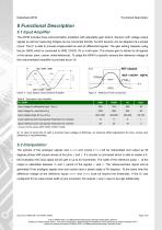
Functional Description 6 Functional Description 6.1 Input Amplifier The AIP40 includes three instrumentation amplifiers with adjustable gain factors. Sensors with voltage output signals as well as measuring bridges can be connected directly. Current sensors can be adapted via a simple circuit. The IC is able to process single-ended as well as differential signals. The gain setting happens using the pin GAIN, which is connected to GND, DVDD, V0 or is left open. The chosen gain is identic for all signals of the sensor (sine, cosine, index/reference). To adapt the AIP40 to specific sensors the reference...
Open the catalog to page 9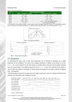
Functional Description Table 7 Reference Point Signal Phase angle reference signal Z Width = 1 Increment = ¼ period Width = 4 Increments = 1 period -22.5° ... 157.5° resp. like REFP/REFN Like the signals REFP/REFN i The position of the reference signal Z at the output is shift if the digital hysteresis is active. For interpolation rates 40 and 20 this shift is 1/40 of the sine period = 9°, and for all other rates the shift is 1/32 of the sine period = 11.25°. Forward: cosine before sine U Figure 6 Input Signals Interpolation Figure 7 Output Signals Interpolation 6.3 Hysteresis For eliminating...
Open the catalog to page 10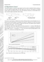
Functional Description 6.4 Edge Distance Control The minimum distance tpp at which the output signals A and B can switch is adjustable. After the switching of one of the outputs the following edge of the other signal occurs if the time t pp was passed. So a following counter is able to count without error also in case of fast distortions. But there is no synchronisation with a clock. Usually the edges are generated without a delay. A A and B switch at same time → input frequency too high Figure 9 Minimum Edge Distance The maximum input frequency is defined by the minimum A/B-edge distance and...
Open the catalog to page 11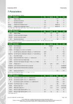
7 Parameters Table 8 Absolute Maximum Ratings Symbol Supply voltage Operating temperature Storage temperature Voltage at the configuration inputs Voltage at the analogue inputs Pins SINP, SINN, COSP, COSN, REFP, REFN, 2) Pins RT, RHYST, GAIN, CFG0, CFG1, 3) t < 250ms, T < 60°C Table 9 Operating Conditions Symbol VDD Supply voltage Current consumption analogue Current consumption digital Operating temperature Minimal temperature and maximal voltage are not allowed at the same time; If TOP < -15°C then VDD must be ≤ 5.25V Table 10 Parameters Analogue Symbol Input impedance AC-Voltage at SMON and...
Open the catalog to page 12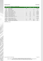
Table 12 Parameters Configuration / Parameters Digital Symbol I(DIG) VTH(L-O) Output current digital Clamping voltage if open VTH(RHyst Threshold voltage L/H, Pin RHYST ) Configuration resistor edge distance R(RHYST) Configuration resistor hysteresis R(RT) Threshold voltage L / open Unit %DVDD VTH(O-V0) Threshold voltage open / V0 Document: 43800-DB-1-5-E-AIP40_AMAC © 2017 AMAC ASIC- und Mikrosensoranwendung Chemnitz GmbH Date: 26/01/17 Subject to change without notice · Any kind of duplication, reprocessing and translation of this document as well as excerpts from it require the written permission...
Open the catalog to page 13All AMAC ASIC - und Mikrosensoranwendung Chemnitz GmbH catalogs and technical brochures
 GC-IP200
31 Pages
 GC-IP201 / GC-IP201(B)
59 Pages
 GC-IP1000B
33 Pages
 GC-NIP
65 Pages
 AM-IP4k
54 Pages
 AM-CVC2D
36 Pages
 Level shifter GC-LS
13 Pages
 GC-IP2000
51 Pages
- Acceleration sensor
- Single-axis accelerometer
- Programmable amplifier
- Photodiode microchip
- 2-channel amplifier
- Vibrating accelerometer
- Digital output accelerometer
- Digital microchip
- Power integrated circuit
- Programmable integrated circuit
- Interpolator
- Measuring system interpolator
- Interpolator with ABZ interface
- Interpolator with BiSS interface