Catalog excerpts

SYSTEM INFO
Open the catalog to page 5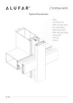
SYSTEM INFO System Characteristic Mullion Condensation Gap EPDM Inner Glass Gasket PVC Thermal Barrier EPDM Central Gasket EPDM Outer Glass Gasket Pressure Plate Outer Cap Transom
Open the catalog to page 7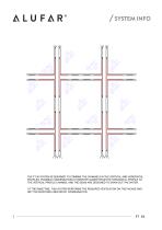
SYSTEM INFO THE FT 50 SYSTEM IS DESIGNED TO COMBINE THE CHANNELS IN THE VERTICAL AND HORIZONTAL PROFILES. POSSIBLE CONDENSATION IS HOWEVER GUIDED FROM THE HORIZONTAL PROFILE TO THE VERTICAL PROFILE CHANNEL AND THE SIGNS ARE DESIGNED TO DRAIN OUT THE WATER. AT THE SAME TIME, THIS SYSTEM PERFORMS THE REQUIRED VENTILATION ON THE FACADE AND DRY THE MOISTURE CREATED BY CONDENSATION.
Open the catalog to page 8
STRUCTURAL CALCULATION
Open the catalog to page 9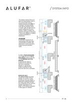
TRAPEZOIDAL (2 SUPPORT POINTS) TRAPEZOIDAL (2 SUPPORT POINTS) ROLLING FIXED THREE-COLUMN (3 SUPPORT POINTS) IMPORTANT NOTE: Τhe distance between the fixing brackets, the number of fixing brackets, as well as any special requirements regarding stability of the facade must always be taken into consideration by the structural engineer responsible for the project, as the solutions presented in these pages are indicative. A mullion is fixed permanently only at one point and at one or more points in fixed in such way so that dilatation not to be impaired. In case that the mullion is anchored at...
Open the catalog to page 10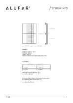
SYSTEM INFO Example 3 Installation height: 8 - 20 m Wind load: 96 Kp/m² Ηeight : 3500 mm Maximum deflection of insulating glass pane: 8 mm Distance between 2 mullions a',b' Required moment of inertia, Jx, is: 4 Jx = Ja +Jb = 80.5 cm As the wind load is 96Kp/m² the moment of inertia has to be multiplied by the correction factor 1.6: 4
Open the catalog to page 11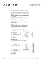
SYSTEM INFO SELECTION OF THE PROPER MULLION The selection of the proper aluminium section of a transom and/ or of a mullion is in accordance to DIN 18056, for a permissible deflection of Η/300 in the distance between supports, considering the wind pressure, the position and the height of the building,as stated in DIN 1055 part 4. SELECTION OF THE PROPER MULLION, SUBJECTED TO WIND LOAD Type of loading: single span beam subjected to trapezoidal loading or triangular loading, twin span beam subjected to rectangular loading TRAPEZOIDAL LOAD The moment of inertia of a mullion, supported at two...
Open the catalog to page 12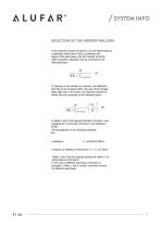
SYSTEM INFO SELECTION OF THE PROPER MULLION If the required moment of inertia Jx is to be determined for a deflection other than H/300, e.g between the edges of the glass panes, the the moment of inertia which has been evaluated must be corrected by the following factor: If, because of the division by transoms, the deflection limit has to be complied within the case of the longest glass edge (Hg) in the frame, the required moment of inertia must be corrected by the following factor: In tables 2 and 4 the required moment of inertia Jx was evaluated for a wind load of 60 Κp/m² and deflection...
Open the catalog to page 13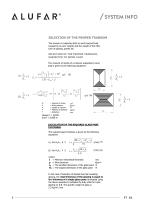
SYSTEM INFO SELECTION OF THE PROPER TRANSOM The transom is subjected both to wind load,self load (caused by its own weight) and the weight of the infill, such as glazing, panels etc. SELECTION OF THE PROPER TRANSOM, SUBJECTED TO WIND LOAD The moment of inertia of a transom subjected to wind load is given by the following equations: Moment of inertia Wind pressure Lenght of transom Μodulus of Elasticity Deflection CALCULATION OF THE REQUIRED GLASS PANE THICKNESS The required pane thickness is given by the following equations: where: t = Minimum theoretical thickness p = Wind pressure Lg =...
Open the catalog to page 14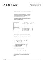
SYSTEM INFO SELECTION OF THE PROPER TRANSOM SELECTION OF THE PROPER TRANSOM SUBJECTED BOTH TO THE WEIGHT OF THE OVERHEAD GLASS PANE, AS WELL AS, TO SELF LOAD 1) The required moment of inertia of a transom due to the weight of the glazing is given by: G = weight of glass pane f1 = Lt/300 και f1<0.003 Lt = Length of transom Suggested distance (α) of the setting blocks of the glass pane : á= 0.150 m 2) The required moment of inertia of a transom subjected to self weight loading is given by: q = Weight of transom per linear meter Kp/m Lt = Length of the transom m f 2 = Lt/300 and <0.003 m Total...
Open the catalog to page 15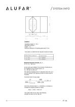
SYSTEM INFO 3.6 m Example 1 Installation height: 8 - 20 m Wind load: 96 Kp/m² Ηeight : 3 m Maximum deflection of insulating glass pane: 8 mm From table 2 to determine the required moment of inertia: Distance between 2 mullions a',b' Required moment of inertia, Jx, is: 4 Jx = Ja +Jb = 101.6 cm As the wind load is 96Kp/m² the moment of inertia has to be multiplied by the correction factor 1.6: 4 Jx = 101.6x1.6=162.6 cm The maximum bending arrow f is required to be 8 mm, so it must be checked if the required moment of inertia must be increased: Correction factor for pane edge : Since the...
Open the catalog to page 16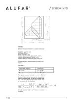
SYSTEM INFO Example 2 Selection of required transom in a complex construction Installation height: 0 - 8 m Wind load: 60 Kp/m² Ηeight of structure : 5 m Maximum dimension of the glass pane Hg : 2.9 m Maximum distance between mullions: 2.9 m Maximum deflection of insulating glass pane: 8 mm 1. Determination of required moment of inertia for the mullion From table 2: Distance between 2 mullions a',b' The required moment of inertia is: Jx = Ja +Jb = 733.9 cm Because of the division by transoms, the deflection limit has to be complied within the case of the longest glass edge in the frame, the...
Open the catalog to page 17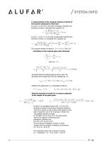
SYSTEM INFO 2. Determination of the required moment of inertia of the transom subjected to wind load As L/ho=1 (2.9/ 2.9=1) the load is triangular, therefore the moment of inertia is evaluated from equation (5). As L/ho>1 (2.9/ 2.1=1) the load is trapezoidal, therefore the moment of inertia Jd is evaluated from equation (6). The required moment of inertia is: Jx = Jc +Jd = 144.5 cm Calculation of the required glass pane thickness As double thermal insulating glazing will be used, the thickness of the single pane must be multiplied by 1.5: Weight of the glass pane, G, is calculated as...
Open the catalog to page 18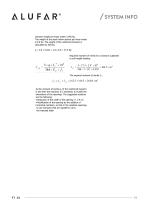
SYSTEM INFO transom weight per linear meter 2.492 Kp. The weight of the steel hollow section per linear meter is 9.9 Kp. The weight of the reinforced transom is calculated as follows: q = 2.9 x 3.032 + 2.9 x 9.9 = 37.5 Kp Required moment of inertia for a transom subjected to self weight loading: The required moment of inertia Jy : As the moment of inertia Jy of the reinforced transom is less than the required, it is necessary to modify the dimensions of the openings. The suggested solutions are the following: · Reduction of the width of the opening (< 2.9 m) · Modification of the opening by...
Open the catalog to page 19
