Catalog excerpts

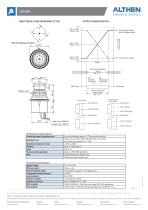
H25JBM DIRECTION OF LEVER OPERATION (O TYPE) DIRECTION OF LEVER OPERATION (O DIRECTIONOF LEVER OPERATION (O TYPE) TYPE) OUTPUT CHARACTERISTICS OUTPUT CHARACTERISTICS OUTPUT CHARACTERISTICS OUT : Xa,Ya (Single output) OUT : Xa,Ya (Single output) : Xb,Yb (Parallel output) : Xb,Yb (Parallel output) Mark for deciding a position Mark for deciding a position Output voltage Output voltage OUT : Xb,Yb (Cross output) OUT : Xb,Yb (Cross output) Center Center Mechanical operating Mechanical operating angle angle Abt. ± 17° Abt. ± 17° Effective electrical Effective electrical rotating angle rotating angle Abt. ± 17° Abt. ± 17° Rubber cover Rubber cover OUT OUT Xb (Orange) Xb (Green) Yb (Orange) Yb (Green) ・Single output ・Single output ・Parallel output ・Parallel output ・Cross output ・Cross output GND(Gray) GND(Gray) Mechanical Specifications Mechanical Specifications Lead wires (AWG24) Lead wires (AWG24) Length, abt. 300mm Length, abt. 300mm Controlling range of operating lever Controlling range of operating lever Operating force Operating force Operating temperature range Operating temperature range Vibration Vibration Shock Shock Mechanical life expectancy Mechanical life expectancy Mass Mass Electrical Specifications Electrical Specifications Applied voltage Applied voltage Effective output Effective output Electrical rotating angle Electrical rotating angle Independent linearity tolerance Independent linearity tolerance Load resistance Load resistance Dielectric strength Dielectric strength Insulation resistance Insulation resistance EMS durability EMS durability ESD durability ESD durability +5V(Brown) +5V(Brown) OUT-Xa(Red) OUT-Xa(Red) OUT-Xb(Orange) OUT-Xb(Orange) GND(Gray) GND(Gray) OUT-Ya(Yellow) OUT-Ya(Yellow) OUT-Ya(Yellow) OUT-Ya(Yellow) OUT-Yb(Green) OUT-Yb(Green) Omni-directionally approx. ± 17°from center position Omni-directionally approx. ± 17°from center position Spring return device (Automatically return to center) Spring return device (Automatically return to center) X&Y directions: Approx. 1N ~ 2.5N X&Y directions: Approx. 1N ~ 2.5N -20℃~+60℃ -20℃~+60℃ 10Hz ~ 55Hz 98m/s² 10Hz ~ 55Hz 98m/s² 294m/s² 294m/s² Approx. 2,000,000 operations Approx. 2,000,000 operations Single output type: Approx. 22g Single output type: Approx. 22g Dual output type: Approx. 24g Dual output type: Approx. 24g D. C. 5V ± 10% D. C. 5V ± 10% 0.5V ~ 4.5V 0.5V ~ 4.5V X&Y directions: Approx. ± 17°(Approx.34°) X&Y directions: Approx. ± 17°(Approx.34°) ± 3%FS ± 3%FS Over 10kΩ Over 10kΩ 1 minute at A. C. 500V 1 minute at A. C. 500V Over 1,000MΩ at D. C. 500V Over 1,000MΩ at D. C. 500V 100V/m (80MHz ~ 1GHz 1kHz sine-wave 80% AM modulation) 100V/m (80MHz ~ 1GHz 1kHz sine-wave 80% AM modulation) ± 8kV contact ± 15kV aerial discharge (Based on IEC61000-4-2) ± 8kV contact ± 15kV aerial discharge (Based on IEC61000-4-2) The information provided herein is to the best of our knowledge true and accurate, it is provided for guidance only. All specifications are subject to change without prior notification. Althen – Your expert partner in Sensors & Controls | althensensors.com Althen stands for pioneering measurement and custom sensor solutions. In addition we offer services such as calibration, design & engineering, training and renting of measurement equipment. Germany/Austria/Switzerland info@althen.de Benelux sales@althen.nl France info@althensensors.fr Sweden info@althensensors.se
Open the catalog to page 1All Althen Controls catalogs and technical brochures
-
HE2 Series
9 Pages
-
HE1 Series
10 Pages
-
TS2 Series
3 Pages
-
TS1 Series
5 Pages


