- Catalogs
- Altantek Hidrolik Pazarlama ve Tic. A.S.
- R e t u r n - S u c t i o n F i l t e rs
R e t u r n - S u c t i o n F i l t e rs
1 /32Pages

R e t u r n - S u c t i o n F i l t e rs
1 /32Pages
Catalog excerpts
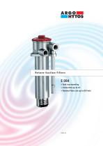
E 084 • Tank top mounting • Connection up to G1 • Nominal flow rate up to 80 l/min
Open the catalog to page 1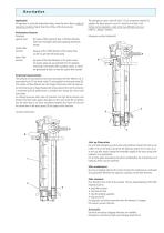
Description Application For operation in units with hydrostatic drives, when the return flow is under all operating conditions higher than the oil flow of the boost pump. Performance features Protection against wear: By means of filter elements that, in full-flow filtration, meet even the highest demands regarding cleanliness classes. Suction filter function: Because of the 100%-filtration of the suction flow, no dirt can get into the boost pump. Return filter function: By means of full-flow filtration in the system return, the pumps above all are protected from dirt particles remaining in the system after...
Open the catalog to page 2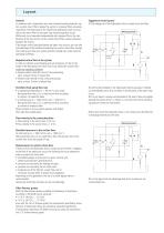
Layout General In machines with a hydrostatic drive and combined working hydraulic system, suction-return filters replace the suction or pressure filters previously required for the feed pump of the closed-loop hydrostatic drive circuit as well as the return filter for the open-loop working hydraulic circuit. While each circuit operates independently with separate filters, the combination of the two circuits via the suction-return filter causes interaction between the circuits. If the design criteria described below are taken into account, you can take full advantage of the benefits provided by the...
Open the catalog to page 3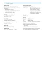
Characteristics Nominal flow rate Up to 80 l/min in return line (see Selection Chart, column 2) Up to 40 l/min Feed pump flow rate (see Layout) The nominal flow rates indicated by ARGO-HYTOS are based on the following features: • closed by-pass valve at ν ≤ 200 mm2/s • element service life > 1000 operating hours at an average fluid contamination of 0,07 g per l/min flow volume • flow velocity in the return lines ≤ 4,5 m/s • flow velocity in the suction lines ≤ 1,5 m/s Viscosity at nominal flow rate • at operating temperature: ν < 60 mm2/s • as starting viscosity: νmax = 1000 mm2/s • at first operation:...
Open the catalog to page 4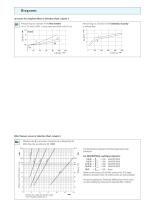
Pressure drop as a function of the kinematic viscosity at nominal flow Pressure drop as a function of the flow volume at ν = 35 mm2/s (00/01 = casing empty without/with hole Ø 4 mm) ∆p-curves for complete filters in Selection Chart, column 3 Filter fineness curves in Selection Chart, column 4 Filtration ratio β as a function of particle size x obtained by the Multi-Pass-Test according to ISO 16889 Filtration ratio β for particles > x µm The abbreviations represent the following β-values resp. finenesses: For EXAPOR®MAX- and Paper elements: 5 E-X = β5 (c) = 200 EXAPOR®MAX 8 E-X = β8 (c) = 200 EXAPOR®MAX...
Open the catalog to page 5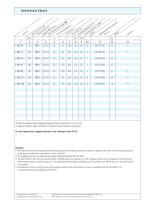
Selection Chart 2 1 nt DX V gr. me PR CV o. e Dia ele of ity of w r e e ac flo see rve n se lte ap sur essur rn s u p tfi r gc res n A ion B etu dro D/c enes en lr g p ing p ol e ldin n ctio ect em no. t ina k ho kin sur ram r fi ne n b lac igh on on om Pres Diag Filte irtrac Crac Sym ep Part C C D N R C We All filters are delivered with a plugged clogging indicator connection M 12 x 1,5 (at P). As clogging indicators either manometers or electrical pressure switches can be used. For the appropriate clogging indicators see catalogue sheet 60.20. Remarks: • The start of the red area respectively the...
Open the catalog to page 6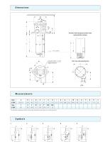
Versions with emergency-suction valve and protection strainer Connection M12 x 1,5 for clogging indicator Port sizes and mounting face Measurements Type * Oil outlet resp. emergency suction has to be under all operating cond. below min. oil level (given by Y)
Open the catalog to page 7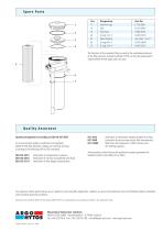
The functions of the complete filters as well as the outstanding features of the filter elements assured by ARGO-HYTOS can only be guaranteed if original ARGO-HYTOS spare parts are used. Quality management according to DIN EN ISO 9001 To ensure constant quality in production and operation, ARGO-HYTOS filter elements undergo strict controls and tests according to the following DIN and ISO standards: Verification of collapse/burst resistance Verification of material compatibility with fluids Verification of flow fatigue characteristics ISO 2942 Verification of fabrication integrity (Bubble Point...
Open the catalog to page 8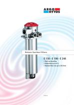
Return-Suction Filters E158 • E198 • E248 • Tank top mounting • Connection up to G1V4 • Nominal flow rate up to 250 l/min
Open the catalog to page 9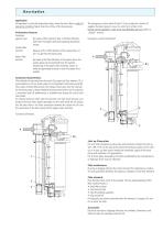
Description Application For operation in units with hydrostatic drives, when the return flow is under all operating conditions higher than the oil flow of the boost pump. Performance features Protection against wear: By means of filter elements that, in full-flow filtration, meet even the highest demands regarding cleanliness classes. Suction filter function: Because of the 100%-filtration of the suction flow, no dirt can get into the boost pump. Return filter function: By means of full-flow filtration in the system return, the pumps above all are protected from dirt particles remainning in the system after...
Open the catalog to page 10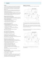
Layout General In machines with a hydrostatic drive and combined working hydraulic system, suction-return filters replace the suction or pressure filters previously required for the feed pump of the closed-loop hydrostatic drive circuit as well as the return filter for the open-loop working hydraulic circuit. While each circuit operates independently with separate filters, the combination of the two circuits via the suction-return filter causes interaction between the circuits. If the design criteria described below are taken into account, you can take full advantage of the benefits provided by the...
Open the catalog to page 11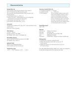
Characteristics Nominal flow rate Up to 250 l/min in return line (see Selection Chart, column 2) Up to 125 l/min Feed pump flow rate (see Layout) The nominal flow rates indicated by ARGO-HYTOS are based on the following features: • closed by-pass valve at ν ≤ 200 mm2/s • element service life > 1000 operating hours at an average fluid contamination of 0,07 g per l/min flow volume • flow velocity in the return lines ≤ 4,5 m/s • flow velocity in the suction lines ≤ 1,5 m/s Viscosity at nominal flow rate • at operating temperature: ν < 60 mm2/s • as starting viscosity: νmax = 1000 mm2/s • at first operation:...
Open the catalog to page 12All Altantek Hidrolik Pazarlama ve Tic. A.S. catalogs and technical brochures
 BD2 + R24
30 Pages
 Hydraulic orbit motor & Accessories
147 Pages
 GPL009
76 Pages
 Steering units
7 Pages
 HPLDF
HPLDF7 Pages
 GPG009
25 Pages
 M4MF
M4MF27 Pages
 MINING Fittings
73 Pages
 FITTINGS
3 Pages
 MINING Hoses
41 Pages
 DRILLING
14 Pages
 Pin Prick Tool
1 Page
 Nipple Inserter
1 Page
 Hydroforming
1 Page
 Marking Machines
1 Page
 Cleaning Machines
1 Page
 UNIFLEX
22 Pages
 Hose Skiving Machines
2 Pages
 HOSES
HOSES30 Pages
 ALTAN ÜRÜN KATALOĞU
55 Pages
 ALUMINIUM HEAT EXCHANGERS
42 Pages
 CRIMPED FITTINGS
138 Pages
 HOSE PROTECTIONS
20 Pages
