- Catalogs
- Alpha Wireless Ltd
- AWT2-3836
AWT2-3836
1 /7Pages
AWT2-3836
1 /7Pages
Catalog excerpts
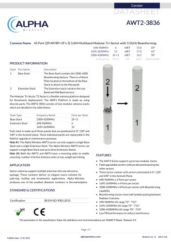
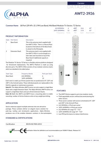
(( ALPHA WIRELESS Common Name 45 Port (2P/4P/8P+1P x 3) 3.6M Multiband Modular Tri-Sector with 3.5GHz Beamforming. PRODUCT INFORMATION Stack Part Name Description 1 Base Stack The Base Stack contains the 3300-4200 Beamforming Sectors. There is a Mount Plate located on the bottom of the Base Stack to attach to the Monopole. 2 Extension Stack The Extension stack contains the Low Band and Mid Band sectors. The Modular Tri-Sector T2 Series is a flexible antenna platform designed for Streetwork deployments. The AWT2 Platform is made up using discrete parts. The AWT2-3836 consists of two modular antenna stacks which are detailed in the table below: Stack Type Base Stack Extension Stack Each stack is made up of three panels that are positioned at 0°, 120° and 240° in the Azimuth plane. These individual panels are replaceable in the field for upgrade or maintenance purposes. Note #1: The Alpha Wireless AWT2 series can only support a single Base Stack and a single Extension Stack. The Alpha Wireless AWT4 series can support a single Base Stack and up to three Extension Stacks. Note #2: Both the AWT2 and AWT4 have a mounting plate to enable mounting number of Active Antenna units on top, weight permitting. FEATURES APPLICATION Sector antennas support multiple antennas into one attractive package. These canisters deliver an elegant macro solution for pole-top, rooftop and streetworks applications. Alpha Wireless produces one of the smallest diameter canisters in the marketplace. Certification BS EN ISO 9001:2015 • The AWT2 Series supports up to two modular stacks. • Field upgradable sectors without decommissioning the other sectors. • Three sector canister with sectors orientated at 0°, 120° and 240° in the Azimuth Plane • 3300-4200MHz x 8 Ports per sector with Beamforming capability • Beamforming sectors have half lambda spacing between Radiator Columns. • Low PIM performance to reduce interference. The parameters in this specification follow the definitions and recommendations per NGMN P-Basta, Release 9.6.
Open the catalog to page 1
ALPHA WIRELESS Radiation Pattern Files For radiation pattern files, please login at www.alphawireless.com Publish Date: 21.02.2025 alphawireless.com Revision no: 12 (BF-6 C
Open the catalog to page 2
TECHNICAL SPECIFICATION Representative Pattern Files For radiation pattern files, please login at www.alphawireless.com Publish Date: 21.02.2025 alphawireless.com Revision no: 12 (BF-6 Col)
Open the catalog to page 3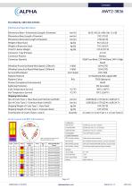
TECHNICAL SPECIFICATION Mechanical Specifications Array Layout and RET Information Total Quantity Twelve RET Motor Controllers Note Coloured box sizes do not represent antenna sizes Inside antenna radome housing Pair of AISG 8 Pin DIN connectors, one male, one female AISG Serial Number Three pairs of AISG 8 Pin DIN connectors, one per sector On connector plate located at bottom of antenna Input Voltage Power Idle Mode Power Active Mode
Open the catalog to page 4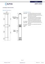
AWT2-3836 TECHNICAL SPECIFICATION Mechanical Illustration Description of Parts Base Stack This contains the Antenna Sectors. Mounted onto the Base Stack Interface. The top of the Base Stack has a mounting flange onto which the Extension Stack is mounted. Extension Stack This contains the Antenna Sectors. Mounted onto the Base Stack . The bottom of the Base Stack has a mounting flange onto which the Extension Stack is mounted to the base stack. RF Jumpers Feeders from the Radio Cabinet feed directly Base Stack into the connectors located at the bottom of the Base Stack. RF Jumpers RF Jumpers are...
Open the catalog to page 5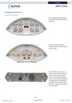
AWT2-3836 TECHNICAL SPECIFICATION Connector Plate Images Showing High Band (Beamforming) Connector Plate located at bottom of Base Stack. Showing Low Band / Mid Band Connector Plate located at bottom of Extension Stack. Each RET Motor is located at the bottom of each antenna sector as part of the Connector Plate. Each RET motor can be accessed individually and if necessary replaced individually by releasing two screws and sliding out the RET Motor Cartridge. A new RET Motor Cartridge can be slid back in as replacement. Page 6/7 Publish Date: 21.02.2025
Open the catalog to page 6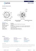
AWT2-3836 TECHNICAL SPECIFICATION Mounting Flange Mounting Kit Tilt Range Mounting Kit Pole Diameter Galvanized Steel Ordering Info Order Code - Antenna Enclosed Remote Electrical Tilt (eRET) with 4.3-10 Connectors. Order Code - Accessories RF Jumper Cable, connector types 4.3-10 (m) / N-Type (m), length 2 metres (6'6") RF Jumper Cable, connector types 4.3-10 (m) / Nex10 (m), length 2 metres (6'6") Portable AISG Controller AISG Jumper Cable Lengths 3 metres (9' 10") AISG Jumper Cable Lengths 10 metres (32' 9") Enquiries Global Headquarters Ashgrove Business Centre, Ballybrittas, Portlaoise, R32...
Open the catalog to page 7All Alpha Wireless Ltd catalogs and technical brochures
 AW3625-M-F-G-V2
6 Pages
 AW3464-T0-F
6 Pages
 AW3821-T0-F
5 Pages
 AW3826-T0-F
5 Pages
 AW3848-T0-F
5 Pages
 AW3939-T0-F
5 Pages
 AW3941-T0-F
5 Pages
 AW3924-T0-F
5 Pages
 AW3913-E-F-ZB
5 Pages
 AWL4001
7 Pages
 AWL4003
7 Pages
 AWL4002
7 Pages
 AW4032-T0-F-BL
6 Pages
 AWL4015-T0-F-BL-V2
6 Pages
 AWT2-3910
6 Pages
 AWT2-3926
6 Pages
 AWT2-3871
6 Pages
 AWT4-3997
5 Pages
 AWT2-3927
6 Pages
 AWC8021
7 Pages
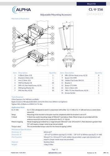 CL-V-156
2 Pages
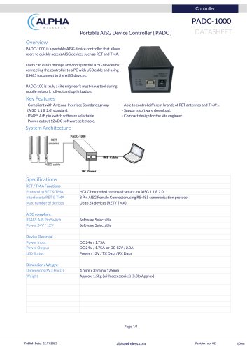 PADC-1000
1 Page
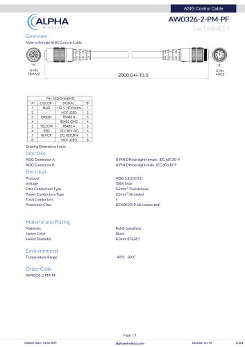 AW0326-2-PM-PF
1 Page

- Programmable logic controller
- Cable assembly
- Compact housing
- Power distribution box
- Modular housing
- Network housing
- RS485 programmable logic controller
- Compact programmable logic controller
- Monitoring housing
- Rugged housing
- Enclosure for telecom applications
- UV-resistant enclosure
- IP55 enclosure
- Cooling housing
- Straight cable harness
- Antenna enclosure
- Wall-mounted support
- Pole mounting support
- Secure enclosure