
- Catalogs
- Alpha Moisture Systems Ltd
- Model 6020 User Manual

- Company
- Products
- Catalogs
- News & Trends
- Exhibitions
Model 6020 User Manual

Model 6020 User Manual
The Model 6020 is a sophisticated dewpoint hygrometer suitable for multi-species gases and natural gas. It features a large LED display, a four-button keypad, selectable engineering units, hot keys for quick access, visual alarms, an AutoCal function for sensor calibration, and options for digital output and external alarms. It is available in both AC and DC powered models.
The Model 6020 operates at hazardous voltages and must be earthed. It requires a 1 amp fuse and should not be connected to power if damaged. Installation should be performed by qualified personnel, and the unit must be isolated before maintenance. The device should not be exposed to water or harsh cleaners.
The interface includes a membrane keyboard with four keys and visual indicators for alarms and units. The primary display shows the current moisture value, while alarms are indicated by LEDs and remote signaling.
For a quick setup, follow these steps: unpack the unit, read safety instructions, prepare the installation site, wire the display unit, insert the sensor, purge the gas, check connections, and power up the unit. Allow the display to stabilize before taking readings.
The Model 6020 has specific moisture and temperature range limits. The enclosure is DIN style with specific dimensions for panel installation.
Mechanical installation requires a specific cut-out size and panel thickness for weatherproof sealing. Electrical installation involves connecting the sensor input, adjusting the cable compensation potentiometer, and ensuring proper wiring for power supply and communication ports.
The piping schematic includes components like isolation valves, sample tubes, and filter units. The sample should be free of contaminants to avoid sensor damage. The sensor should be installed in a bypass or fast loop for easy maintenance.
The setup for a sample system using the Model 6020 Dewpoint Hygrometer specifies the use of pressure reduction valves depending on whether measurements are taken at atmospheric or full line pressure. A sample pressure gauge is optional but recommended for dew/frost point measurements above atmospheric pressure. The system includes a desiccant chamber for intermittent sampling to prevent moisture ingress, and a flow control valve to maintain a recommended sample flow of 2 to 3 litres/min at NTP.
Before installing the sensor, an initial purge of the sample loop is advised to prevent sensor damage. The procedure involves slowly opening the inlet isolation valve to allow a small flow of air/gas, purging for 15 to 20 minutes, and then installing the sensor. The system may take several hours to reach equilibrium upon initial start-up.
The AutoCal calibration process for sensors with ranges up to +20°C and 0°C dewpoint involves comparing the Model 6020 reading with an external measurement method and adjusting the Autocal potentiometer accordingly. The system is designed to maintain a constant reading at maximum moisture levels.
Instructions are provided for entering numerical values into the Model 6020, including setting alarm levels and changing units. The process involves using specific keys to navigate and set values, with options to view and alter displayed units.
The setup menu allows configuration of various parameters such as moisture units, pressure units, temperature units, and gas type. Detailed instructions are provided for navigating the menu and setting these parameters, including enabling/disabling natural gas measurements and sensor linearisation.
The document explains how to select and view sensor ranges, including the option to view and edit linearisation data points. It provides a table of dew point ranges for different sensor colors and instructions for entering new calibration data.
Catalog excerpts
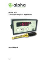
Model 6020 Advanced Dewpoint Hygrometer User Manual
Open the catalog to page 1
This manual should be kept with the Model 6020 Please read this manual carefully from the beginning. You must observe the safety information on page 3 before installation. Document Reference: 1931 - Issue 8 - 21rd December, 2023 © Alpha Moisture Systems Ltd.
Open the catalog to page 2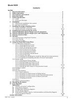
General Information Safety Information User Interface and Controls Quick Start Guide Outline Specification 5.1 Limits 5.2 Enclosure DIN Style 6 Installation 6.1 Mechanical installation into a panel 6.2 Electrical installation 7 Installing the air/gas sampling system 7.1 Piping installation schematic 7.2 Piping schematic component index 8 Installing and commissioning the sensor 9 AutoCal Calibration (Sensor Ranges up to 0 C dewpoint) 10 AutoCal Calibration (Sensor Ranges up to +20 C dewpoint) 11 Entering numerical data 12 Hot keys 12.1 Lock Hot keys using Panel Function 12.2 Units Hot key 12.3...
Open the catalog to page 3
General information The Model 6020 is the next level in online dewpoint hygrometry for multi-species gases and natural gas. With powerful functions and features available that allow the user to set detailed configurations and parameters for more continuous measurement control. This makes the Model 6020 the advanced choice with the following features and benefits: Large easy to read 5-digit LED display Four-button membrane keypad Six selectable engineering units Three hot keys to enable rapid access Two visual alarms LEDS AutoCal (Automatic Calibration) function to perform periodic auto-calibration...
Open the catalog to page 4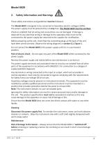
Safety Information and Warnings These safety instructions and guidelines must be followed. The Model 6020 is designed to be connected to hazardous electric voltages (240V). The power supply must be protected by a 1 amp fuse. The Model 6020 must be earthed. Check to establish that all wiring and connections are not damaged. If damage is observed to any electrical wiring or damage to the apparatus they must not be connected to the power supply but returned to the supplier for rectification. Before powering up the unit, check that the connecting plugs at the back of the unit have been wired correctly....
Open the catalog to page 5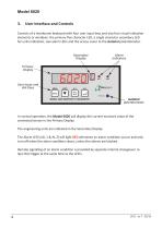
User Interface and Controls Consists of a membrane keyboard with four user input keys and also four visual indication elements or windows: the primary five character LED, a single character secondary LED for units indication, two alarm LEDs and the access cover to the AutoCal potentiometer. Secondary Display Primary Display User Input and Hot Keys Alarm Indicators MODEL 6020 DEWPOINT HYGROMETER AutoCal potentiometer In normal operation, the Model 6020 will display the current moisture value of the connected sensor in the Primary Display. The engineering units are indicated in the Secondary Display....
Open the catalog to page 6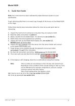
Quick Start Guide Note: Your instrument has been calibrated by Alpha Moisture Systems to your specification. To get started quickly there is no need to go through all the menus on the Model 6020 at this stage. Follow these step by step instructions below for a fast set up and quick start to measuring. 1. 2. 3. 4. 5. Unpack the Control Unit and Sensor only when they are ready to install. Read the safety instructions in section 2. Make a location for the Model 6020 - For dimensions see section 6.1. Make ready and seal all pipework for sampling. Unpack and wire up the Model 6020 display unit, see...
Open the catalog to page 7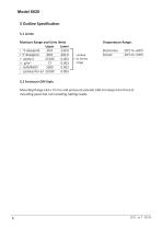
Moisture Range and Units limits Upper Lower C °C dewpoint 20.0 -130.0 F- °F dewpoint 68.0 -202.0 P ppm(v) 23100 0.001 g g/m3 17 0.001 L lb/MMSCF 1000 0.001 = ppm(w) for air 23100 0.001 Temperature Range: Limited to Sensor range Electronics Sensor Mounting flange 144 x 72 mm and enclosure extends 108 mm deep from front of mounting panel but not including cabling needs.
Open the catalog to page 8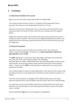
6.1 Mechanical installation into a panel Make a cut-out in the donor panel 138.0 x 68.0 mm (DIN 43700). The maximum panel thickness is 8mm. If an effective IP65 weatherproof seal is required, the minimum recommended panel thickness is 2.5 mm. Pass the instrument case through the cut-out in the donor panel and attach the two retaining screws to the studs on either side of the case making use of the supplied gasket. Tighten the retaining screws onto the back of the donor panel until the instrument is clamped securely in position. The screws must be tightened sufficiently to affect a seal between the...
Open the catalog to page 9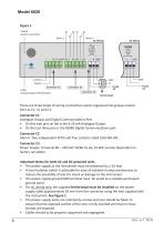
Coaxial Sensor Connection Cable Compensation Potentiometer Ferrite bead There are three banks of wiring connections points organised into groups named here as C1, C2 and C3. Connector C1 Analogue Output and Digital Communications Port • On first two pins on left is the 4-20 mA Analogue Output. • On the last three pins is the RS485 Digital Communications port. Connector C2 Alarms: Two independent SPCO volt free contacts rated 10A/240 VAC. Connector C3 Power Supply: Universal 90 – 250 VAC 50/60 Hz, or, 24 VDC version dependant on factory set option. Important Notes for both AC and DC powered units....
Open the catalog to page 10
Installing the air/gas sampling system The piping installation schematic diagram (see section 7.1) shows all components that could be used in a dry gas measurement application. Not all the items shown will be required for every installation. Care should be taken to ensure that the sample presented to the measuring sensor is not contaminated with any component that will damage, contaminate or affect the sensor in a way that will impair the system accuracy. It is strongly recommended that the sample should not contain particulate matter, oil or other heavy hydrocarbon condensate. If these components...
Open the catalog to page 11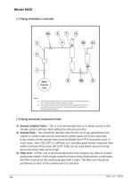
Model 6020 7.1 Piping installation schematic 3 1 Main Process Line The sample point should be on the upper surface of the horizontal pipe, or from a vertical section of pipe, wherever possible. b. The sample tube should run upwards from the sample point. If this is not possible then an inspection port or drain tap should be installed at the lowest point in the system. 7.2 Piping schematic component index 1) Sample Isolation Valve – This is a recommended item as it allows access to the sample system without interrupting the main process line. 2) Sample Tube – This should be stainless steel for...
Open the catalog to page 12All Alpha Moisture Systems Ltd catalogs and technical brochures
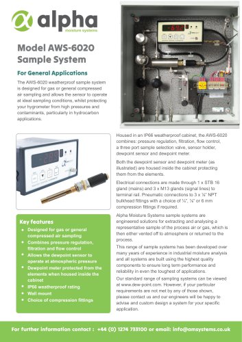
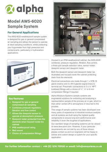 Model AWS-6020 Sample System
3 Pages
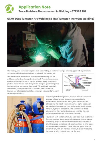
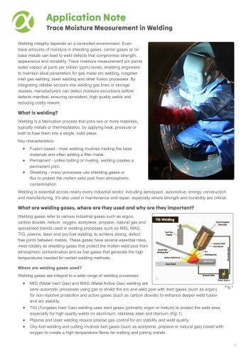 Trace Moisture In Welding
4 Pages
 SADPmini2 User Manual
57 Pages
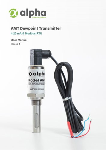
 AMT User Manual
14 Pages
 AMT-Ex User Manual
15 Pages
 PSS User Manual
17 Pages
 SADPmini2-Ex User Manual
86 Pages
 DS1200-Exd-AMT-Ex
3 Pages
 DS1500-Exd
2 Pages
 DS4000-Exd-AMT-Ex
3 Pages
 DSP-FCI Portable Hygrometer
3 Pages
 Model 6020 Exd
4 Pages
 Model 6020
3 Pages
 DS1500
3 Pages






- Digital indicator
- 4-20 mA indicator
- Automatic sampler
- Stainless steel sampler
- Gas sampler
- Sampler for the food industry
- Sampler for the pharmaceutical industry
- Humidity hygrometer
- 4-digit indicator
- Relative humidity hygrometer
- Portable sampler
- Digital hygrometer
- Compact sampler
- Alpha Moisture Systems dew-point transmitter
- Laboratory sampler
- Industrial hygrometer
- Dew-point humidity meter
- Transmitter indicator
- Analog dew-point transmitter