- Catalogs
- Alpha Moisture Systems Ltd
- AMT Modbus RTU Dewpoint Transmitter Instruction Manual
- Company
- Products
- Catalogs
- News & Trends
- Exhibitions
AMT Modbus RTU Dewpoint Transmitter Instruction Manual
1 /28Pages

AMT Modbus RTU Dewpoint Transmitter Instruction Manual
1 /28Pages
Catalog excerpts
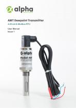
AMT Dewpoint Transmitter 4-20 mA & Modbus RTU User Manual Issue 1
Open the catalog to page 1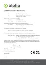
UK & EU Declaration of Conformity We Alpha Moisture Systems Ltd of Network House, 5 Lister Hill, Horsforth, declare under our sole responsibility that: Model Name: AMT Dewpoint Transmitter Conforms with the relevant provisions of the following Directive: 2014/30/EU The Electromagnetic Compatibility Directive Conforms with the relevant UK provisions of the following: Electromagnetic Compatibility Regulations 2016 (S.I. 2016/1091) EMC compliance has been assessed by reference to the following specifications: EN 61326-1:2021 Electrical equipment for measurement, control, and laboratory use. EMC...
Open the catalog to page 2
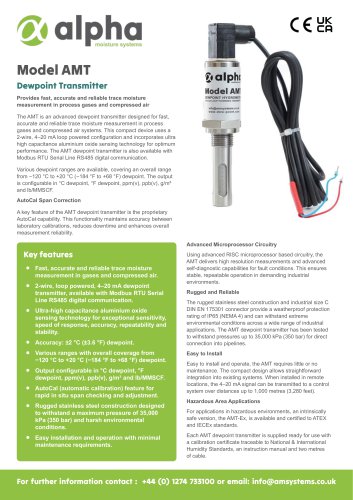
Unpacking Your Alpha Moisture Systems AMT Please examine the AMT package for any damage or mishandling. If any damage is evident please notify the carrier and the Alpha Moisture Systems representative from where this unit was purchased. You should have received (if ordered): • • • • 1 AMT 4-20 mA dewpoint transmitter 1 connecting cable of the length specified in your order or two metres as standard 1 instruction manual 1 calibration certificate If anything is missing, please contact your distributor immediately. Alpha Moisture Systems AMT is a 2-wire, 4-20 mA loop powered transmitter, also available...
Open the catalog to page 4
Corrosive Gases The sensor should not be exposed to corrosive gases (or corrosive contaminants in the gas sample) as these can chemically attack the sensor, impairing calibration accuracy and/or damaging it beyond economic repair. Examples of such gases are mercury (Hg), ammonia (NH3), chlorine (Cl2) etc. Strong oxidising agents such as ozone (O3) should also be prevented from coming into contact with the sensor. It is strongly recommended that the sample should not contain particulate matter, oil or other heavy hydrocarbon condensate. If these components contaminate the sample system and/or...
Open the catalog to page 5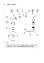
Piping installation MAIN PROCESS LINE NOTES a. The sample point should be on the upper surface of a horizontal pipe or on a vertical section of pipe, where ever possible. b. The sample tube should run, continually, upwards from the sample point. If this is not possible an inspection port or drain tap should be installed at the lowest point in the system. Fig. 1
Open the catalog to page 6
Component Index Sample Isolation Valve - This is a recommended item as it allows access to the sample system without interrupting the main process line. Sample Tube – This should be stainless steel for dry air or gas applications but copper or carbon steel can be used where wetter gases are to be measured. If any section of the sample tube must be flexible then PTFE should be used. In most cases, 3mm OD (1/8”) is sufficient as it provides good system response time within minimum flow. 6mm OD (1/4”) tube can be used where pressure drops across the 3mm tube are too high Filter Unit – A filter unit...
Open the catalog to page 7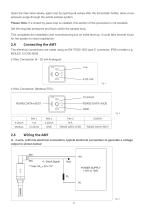
Open the inlet valve slowly, again and by opening all valves after the transmitter holder, allow a low pressure purge through the whole sample system. Please Note. If a closed by-pass loop is installed, this section of the procedure is not possible. Set the required pressures and flows within the sample loop. This completes the installation and commissioning but on initial start-up, it could take several hours for the system to reach equilibrium. The electrical connections are made using an EN175301-803 type C connector, IP66 or better e.g. 2 Wire Connection (4 - 20 mA Analogue) 4 Wire Connection...
Open the catalog to page 8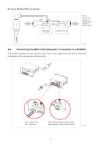
BALANCED PAIR NOTE: The 4-20 mA signal is not available when operating in Modbus mode Connecting the AMT 2-Wire Dewpoint Transmitter to a DS4000 The DS4000 displays a linear readout of the 4-20 mA input signal received from an attached transmitter in the pre-selected moisture units. mA+ = BLUE wire 24v = RED wire Mains Power Supply = Brown (Live), Blue (Neutral) & Green/Yellow (Earth)
Open the catalog to page 9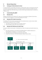
Normal Operation In normal operation, the transmitter will produce a 4-20mA signal, which is proportional to the level of moisture in the gas being monitored. The moisture reading is sampled and updated once per second. The AMT has 3,020 distinct steps over the 4-20mA range corresponding to a resolution of 0.005mA (5 μA) . Dewpoint transmitters with a Modbus RTU output can be connected to a Modbus Client device. This Client can be a gateway or any third-party Modbus RTU Client. Modbus RTU Cable Connection The Modbus RTU link should be operated within the constraints below in order to ensure stable...
Open the catalog to page 10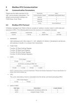
Modbus RTU Communication Communication Parameters Parameter Please see the table opposite for the AMT communication parameters. The default communication settings are 19200 Baud, Even Parity. A Modbus message from Client to Server consists of: address, function (read or write) data and checksum (CRC). The following table shows the structure of a complete command:
Open the catalog to page 11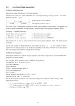
Function Codes Supported 03 Read Holding Registers Description: Read the contents of holding registers. Addresses available are: 4001,4004, 5001. For a full register listing, see Appendix E - Transmitter Modbus Registers Layout. Units Register, Address 4004 The register is READ ONLY. The value in the Units Register exposes the units of the dewpoint measurement. The register can be read by issuing a Read Holding Register Command with Holding register address #4004. There are 7 possible responses: 0 or 6 - Dewpoint value is in °C 3 - Dewpoint value is in ppb(v) 1 - Dewpoint value is in °F 4 - Dewpoint...
Open the catalog to page 12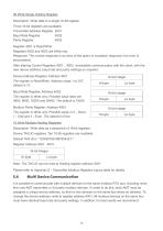
06 Write Single Holding Register Description: Write data to a single 16-bit register. Three 16-bit registers are available: Transmitter Address Register 4001 Baud Rate Register 4002 Register 4001 is Read/Write Registers 4002 and 4003 are Write only Response: The normal response is an echo of the query or exception response if an error is encountered. After altering Control Registers 4001...4003, re-establish communication with the client, with the new device address, baud rate and parity settings as required. Note: The TAG ID can be read at Holding register address 5001. Please refer to Appendix...
Open the catalog to page 13All Alpha Moisture Systems Ltd catalogs and technical brochures
 Model AWS-6020 Sample System
3 Pages
 Trace Moisture In Welding
4 Pages
 Model 6020 User Manual
41 Pages
 SADPmini2 User Manual
57 Pages
 AMT User Manual
14 Pages
 AMT-Ex User Manual
15 Pages
 PSS User Manual
17 Pages
 SADPmini2-Ex User Manual
86 Pages
 DS1200-Exd-AMT-Ex
3 Pages
 DS1500-Exd
2 Pages
 DS4000-Exd-AMT-Ex
3 Pages
 DSP-FCI Portable Hygrometer
3 Pages
 Model 6020 Exd
4 Pages
 Model 6020
3 Pages
 DS1500
3 Pages


- Digital indicator
- 4-20 mA indicator
- Automatic sampler
- Stainless steel sampler
- Gas sampler
- Humidity meter
- Sampler for the food industry
- Sampler for the pharmaceutical industry
- Humidity hygrometer
- 4-digit indicator
- Relative humidity hygrometer
- Digital hygrometer
- Portable sampler
- Compact sampler
- Laboratory sampler
- Alpha Moisture Systems dew-point transmitter
- Industrial hygrometer
- Dew-point humidity meter
- Transmitter indicator
- Analog dew-point transmitter